

generators, replacing boilers. When properly designed and spared, hydrogen plants
can supply steam in an emergency, such as the loss of other boilers.
A typical steam system for an SMR hydrogen plant is illustrated in Fig. 13. Many
configurations are used for these systems, however.
There are three areas where most steam is generated in a hydrogen plant:
• Reforming furnace process outlet. Here, a steam generator/waste heat boiler
(WHB) is installed. The WHB cools the process gases from their exit temperature of 1,350–1,740
F down to the HTS converter inlet temperature of about
700
F. The final temperature is controlled by bypassing hot gas around
1
10
100
Equilibrium % Methane in Dry Gas
20
30
40
60
80
8
6
4
2
Steam/Carbon Ratio
100
Pressure, psig
200
300
400
500
600
700
Temperature, °F
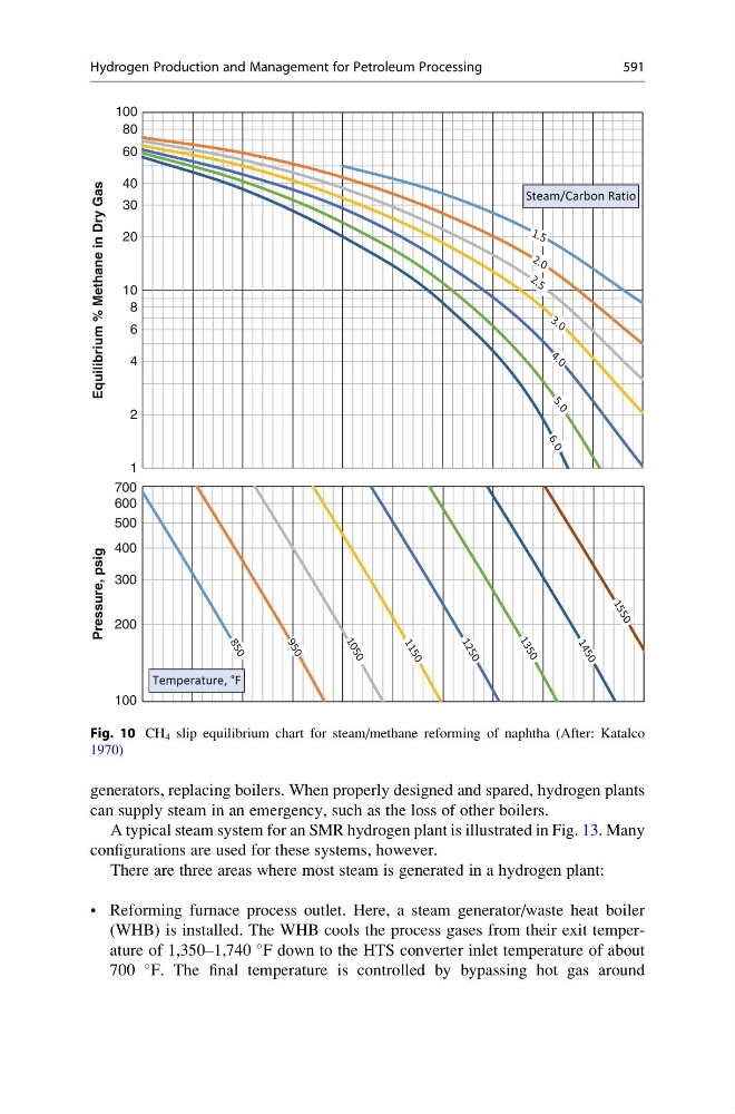
Fig. 10 CH 4 slip equilibrium chart for steam/methane reforming of naphtha (After: Katalco
1970)
Hydrogen Production and Management for Petroleum Processing
591