

the riser into two reaction zones. The first is between the feed injection and the
cycle oil inlet. This zone is characterized by a high mix temperature, a high catalystto-oil ratio, and a very short contact time.
The second zone above the cycle oil inlet operates under more conventional
catalytic cracking conditions. The riser temperature is maintained independently by
the introduction of the regenerated catalyst. Thus an increase in cycle oil leads to a
decrease in riser temperature, which introduces more catalyst; this finally increases
the mix temperature and the catalyst-to-oil ratio and decreases the regenerator
temperature.
The Lift Gas Technology
As described earlier, it is highly desirable to achieve good catalyst/oil mixing as
early and as quickly as possible. The method described to achieve this requires the
preacceleration and dilution of the catalyst stream. Traditionally, steam is the
medium used to maintain catalyst bed fluidity and movement in the riser. Steam,
however, has a deleterious effect on the very hot catalyst that is met in residue
cracking processes. Steam under these conditions causes hydrothermal deactivation
of the catalyst.
Much work has been done in reducing the use of steam in contact with the hot
catalyst. Some of the results of the work showed that if the partial pressure of steam
is kept low, the hydrothermal effects are greatly reduced, in the case of relatively
metal-free catalyst. A more important result of the work showed that light hydrocarbons imparted favorable conditioning effects to the freshly regenerated catalyst.
This was even pronounced in catalysts that were heavily contaminated with metals.
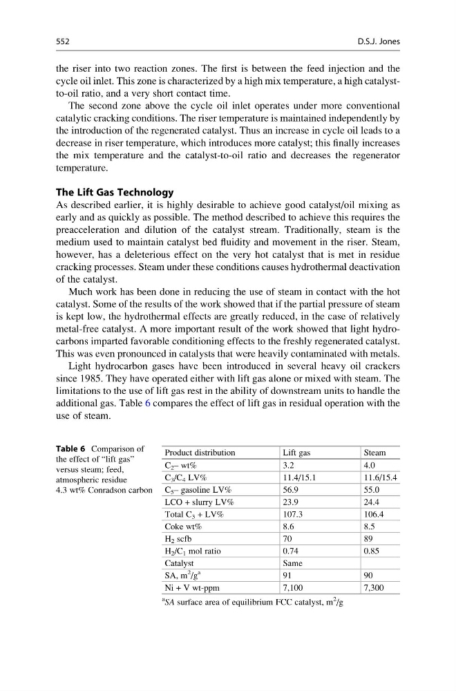
Light hydrocarbon gases have been introduced in several heavy oil crackers
since 1985. They have operated either with lift gas alone or mixed with steam. The
limitations to the use of lift gas rest in the ability of downstream units to handle the
additional gas. Table 6 compares the effect of lift gas in residual operation with the
use of steam.
Table 6 Comparison of
the effect of “lift gas”
versus steam; feed,
atmospheric residue
4.3 wt% Conradson carbon
Product distribution
Lift gas
Steam
C 2 – wt%
3.2
4.0
C 3 /C 4 LV%
11.4/15.1
11.6/15.4
C 5 – gasoline LV%
56.9
55.0
LCO + slurry LV%
23.9
24.4
Total C 3 + LV%
107.3
106.4
Coke wt%
8.6
8.5
H 2 scfb
70
89
H 2 /C 1 mol ratio
0.74
0.85
Catalyst
Same
SA, m
2
/g
a
91
90
Ni + V wt-ppm
7,100
7,300
a
SA surface area of equilibrium FCC catalyst, m
2
/g
552
D.S.J. Jones
cycle oil inlet. This zone is characterized by a high mix temperature, a high catalystto-oil ratio, and a very short contact time.
The second zone above the cycle oil inlet operates under more conventional
catalytic cracking conditions. The riser temperature is maintained independently by
the introduction of the regenerated catalyst. Thus an increase in cycle oil leads to a
decrease in riser temperature, which introduces more catalyst; this finally increases
the mix temperature and the catalyst-to-oil ratio and decreases the regenerator
temperature.
The Lift Gas Technology
As described earlier, it is highly desirable to achieve good catalyst/oil mixing as
early and as quickly as possible. The method described to achieve this requires the
preacceleration and dilution of the catalyst stream. Traditionally, steam is the
medium used to maintain catalyst bed fluidity and movement in the riser. Steam,
however, has a deleterious effect on the very hot catalyst that is met in residue
cracking processes. Steam under these conditions causes hydrothermal deactivation
of the catalyst.
Much work has been done in reducing the use of steam in contact with the hot
catalyst. Some of the results of the work showed that if the partial pressure of steam
is kept low, the hydrothermal effects are greatly reduced, in the case of relatively
metal-free catalyst. A more important result of the work showed that light hydrocarbons imparted favorable conditioning effects to the freshly regenerated catalyst.
This was even pronounced in catalysts that were heavily contaminated with metals.
Light hydrocarbon gases have been introduced in several heavy oil crackers
since 1985. They have operated either with lift gas alone or mixed with steam. The
limitations to the use of lift gas rest in the ability of downstream units to handle the
additional gas. Table 6 compares the effect of lift gas in residual operation with the
use of steam.
Table 6 Comparison of
the effect of “lift gas”
versus steam; feed,
atmospheric residue
4.3 wt% Conradson carbon
Product distribution
Lift gas
Steam
C 2 – wt%
3.2
4.0
C 3 /C 4 LV%
11.4/15.1
11.6/15.4
C 5 – gasoline LV%
56.9
55.0
LCO + slurry LV%
23.9
24.4
Total C 3 + LV%
107.3
106.4
Coke wt%
8.6
8.5
H 2 scfb
70
89
H 2 /C 1 mol ratio
0.74
0.85
Catalyst
Same
SA, m
2
/g
a
91
90
Ni + V wt-ppm
7,100
7,300
a
SA surface area of equilibrium FCC catalyst, m
2
/g
552
D.S.J. Jones