

Calculating the Reclaimer Duty and Size
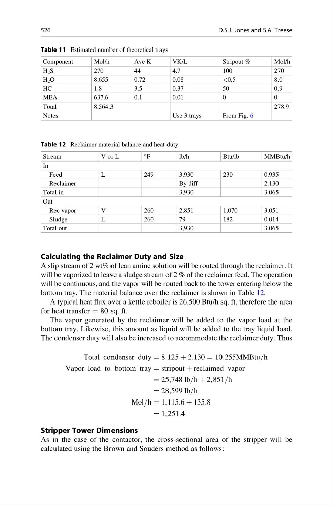
A slip stream of 2 wt% of lean amine solution will be routed through the reclaimer. It
will be vaporized to leave a sludge stream of 2 % of the reclaimer feed. The operation
will be continuous, and the vapor will be routed back to the tower entering below the
bottom tray. The material balance over the reclaimer is shown in Table 12.
A typical heat flux over a kettle reboiler is 26,500 Btu/h sq. ft, therefore the area
for heat transfer = 80 sq. ft.
The vapor generated by the reclaimer will be added to the vapor load at the
bottom tray. Likewise, this amount as liquid will be added to the tray liquid load.
The condenser duty will also be increased to accommodate the reclaimer duty. Thus
Total condenser duty ¼ 8:125 þ 2:130 ¼ 10:255MMBtu=h
Vapor load to bottom tray ¼ stripout þ reclaimed vapor
¼ 25,748 lb=h þ 2,851=h
¼ 28,599 lb=h
Mol=h ¼ 1,115:6 þ 135:8
¼ 1,251:4
Stripper Tower Dimensions
As in the case of the contactor, the cross-sectional area of the stripper will be
calculated using the Brown and Souders method as follows:
Table 11 Estimated number of theoretical trays
Component
Mol/h
Ave K
VK/L
Stripout %
Mol/h
H 2 S
270
44
4.7
100
270
H 2 O
8,655
0.72
0.08
<0.5
8.0
HC
1.8
3.5
0.37
50
0.9
MEA
637.6
0.1
0.01
0
0
Total
8,564.3
278.9
Notes
Use 3 trays
From Fig. 6
Table 12 Reclaimer material balance and heat duty
Stream
V or L
F
lb/h
Btu/lb
MMBtu/h
In
Feed
L
249
3,930
230
0.935
Reclaimer
By diff
2.130
Total in
3,930
3.065
Out
Rec vapor
V
260
2,851
1,070
3.051
Sludge
L
260
79
182
0.014
Total out
3,930
3.065
526
D.S.J. Jones and S.A. Treese
A slip stream of 2 wt% of lean amine solution will be routed through the reclaimer. It
will be vaporized to leave a sludge stream of 2 % of the reclaimer feed. The operation
will be continuous, and the vapor will be routed back to the tower entering below the
bottom tray. The material balance over the reclaimer is shown in Table 12.
A typical heat flux over a kettle reboiler is 26,500 Btu/h sq. ft, therefore the area
for heat transfer = 80 sq. ft.
The vapor generated by the reclaimer will be added to the vapor load at the
bottom tray. Likewise, this amount as liquid will be added to the tray liquid load.
The condenser duty will also be increased to accommodate the reclaimer duty. Thus
Total condenser duty ¼ 8:125 þ 2:130 ¼ 10:255MMBtu=h
Vapor load to bottom tray ¼ stripout þ reclaimed vapor
¼ 25,748 lb=h þ 2,851=h
¼ 28,599 lb=h
Mol=h ¼ 1,115:6 þ 135:8
¼ 1,251:4
Stripper Tower Dimensions
As in the case of the contactor, the cross-sectional area of the stripper will be
calculated using the Brown and Souders method as follows:
Table 11 Estimated number of theoretical trays
Component
Mol/h
Ave K
VK/L
Stripout %
Mol/h
H 2 S
270
44
4.7
100
270
H 2 O
8,655
0.72
0.08
<0.5
8.0
HC
1.8
3.5
0.37
50
0.9
MEA
637.6
0.1
0.01
0
0
Total
8,564.3
278.9
Notes
Use 3 trays
From Fig. 6
Table 12 Reclaimer material balance and heat duty
Stream
V or L
F
lb/h
Btu/lb
MMBtu/h
In
Feed
L
249
3,930
230
0.935
Reclaimer
By diff
2.130
Total in
3,930
3.065
Out
Rec vapor
V
260
2,851
1,070
3.051
Sludge
L
260
79
182
0.014
Total out
3,930
3.065
526
D.S.J. Jones and S.A. Treese