

turn, and the optimization of the unit requires a dynamic model that pushes the
cracker to multiple limits. It should be noted that the catalyst is a variable. Activity
can be adjusted over a wide range, and product selectivities can be adjusted as
needed.
Fluid Cracking Catalysts
The FCC process has been shaped and reshaped to accommodate the advances
made in fluid cracking catalysts. Early catalysts were relatively inactive and
amorphous in nature and required a lot of recycle of the uncracked feed to achieve
the desired conversions. Carbon on regenerated catalyst was usually around 0.3–0.6
wt% and had little effect on unit performance. In the early 1960s, zeolite-containing
catalysts were introduced that were much more active and selective than previous
catalysts but required the removal of residual coke for optimum commercial
performance. This allowed the refiner to substitute fresh feed for the large amounts
of recycle being used and resulted in greatly expanded capacity and gasoline yields.
The preferred FCC zeolite is a crystalline silica-alumina compound that has the
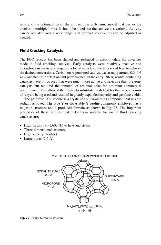
sodium removed. The type Y or ultrastable Y zeolite commonly employed has a
faujasite structure and a produced formula as shown in Fig. 25. The important
properties of these zeolites that make them suitable for use in fluid cracking
catalysts are:
• High stability (>1,600
F) to heat and steam
• Three-dimensional structure
• High activity (acidity)
• Large pores (7.5 A ˚ )
SODALITE CAGE
2.2 A
SUPER-CAGE
13.0 A
MICROPORE
7.5 A
Na x (AIO) x (SiO 2 ) 192-x (H2O) y
x : 54 - 58
Y ZEOLITE IS A 3-D FRAMEWORK STRUCTURE
Fig. 25 Faujasite zeolite structure
294
W. Letzsch
cracker to multiple limits. It should be noted that the catalyst is a variable. Activity
can be adjusted over a wide range, and product selectivities can be adjusted as
needed.
Fluid Cracking Catalysts
The FCC process has been shaped and reshaped to accommodate the advances
made in fluid cracking catalysts. Early catalysts were relatively inactive and
amorphous in nature and required a lot of recycle of the uncracked feed to achieve
the desired conversions. Carbon on regenerated catalyst was usually around 0.3–0.6
wt% and had little effect on unit performance. In the early 1960s, zeolite-containing
catalysts were introduced that were much more active and selective than previous
catalysts but required the removal of residual coke for optimum commercial
performance. This allowed the refiner to substitute fresh feed for the large amounts
of recycle being used and resulted in greatly expanded capacity and gasoline yields.
The preferred FCC zeolite is a crystalline silica-alumina compound that has the
sodium removed. The type Y or ultrastable Y zeolite commonly employed has a
faujasite structure and a produced formula as shown in Fig. 25. The important
properties of these zeolites that make them suitable for use in fluid cracking
catalysts are:
• High stability (>1,600
F) to heat and steam
• Three-dimensional structure
• High activity (acidity)
• Large pores (7.5 A ˚ )
SODALITE CAGE
2.2 A
SUPER-CAGE
13.0 A
MICROPORE
7.5 A
Na x (AIO) x (SiO 2 ) 192-x (H2O) y
x : 54 - 58
Y ZEOLITE IS A 3-D FRAMEWORK STRUCTURE
Fig. 25 Faujasite zeolite structure
294
W. Letzsch