

Virtually all of the cracking takes place in the feed riser which connects to a catalyst/
vapor separator. The hot catalyst is discharged into the catalyst stripper while the
vapor is routed through secondary cyclones to remove any remaining catalyst and
then to the main fractionator and gas plant for separation of the products.
The spent catalyst enters a multistage stripper where the absorbed hydrocarbons
are displaced with steam and leave with the product from the overhead of the
reactor. This prevents unwanted hydrocarbons from entering the regenerator, consuming air, and possibly causing excessive catalyst deactivation. Staging is
Table 2 Typical resid
cracking yields
Unit A
Unit B
Feed properties
API gravity
0.922
0.963
Conradson carbon
3.8
8.0
Ni + V
4
7.5
wt%
wt%
Conversion
70.0
70.0
Dry gas
2.1
3.4
LPG
15.3
14.4
Gasoline
46.2
43.1
LCO
16.3
16.0
Decant oil
13.7
14.0
Coke
6.5
9.1
1985
0
500
1000
1500
2000
2500
3000
3500
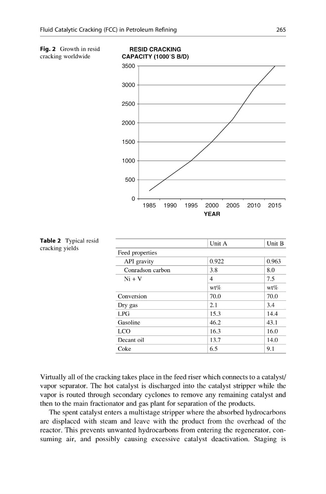
RESID CRACKING
CAPACITY (1000ЈS B/D)
1990 1995 2000
YEAR
2005 2010 2015
Fig. 2 Growth in resid
cracking worldwide
Fluid Catalytic Cracking (FCC) in Petroleum Refining
265
vapor separator. The hot catalyst is discharged into the catalyst stripper while the
vapor is routed through secondary cyclones to remove any remaining catalyst and
then to the main fractionator and gas plant for separation of the products.
The spent catalyst enters a multistage stripper where the absorbed hydrocarbons
are displaced with steam and leave with the product from the overhead of the
reactor. This prevents unwanted hydrocarbons from entering the regenerator, consuming air, and possibly causing excessive catalyst deactivation. Staging is
Table 2 Typical resid
cracking yields
Unit A
Unit B
Feed properties
API gravity
0.922
0.963
Conradson carbon
3.8
8.0
Ni + V
4
7.5
wt%
wt%
Conversion
70.0
70.0
Dry gas
2.1
3.4
LPG
15.3
14.4
Gasoline
46.2
43.1
LCO
16.3
16.0
Decant oil
13.7
14.0
Coke
6.5
9.1
1985
0
500
1000
1500
2000
2500
3000
3500
RESID CRACKING
CAPACITY (1000ЈS B/D)
1990 1995 2000
YEAR
2005 2010 2015
Fig. 2 Growth in resid
cracking worldwide
Fluid Catalytic Cracking (FCC) in Petroleum Refining
265