

Continuous Catalyst Regeneration Units
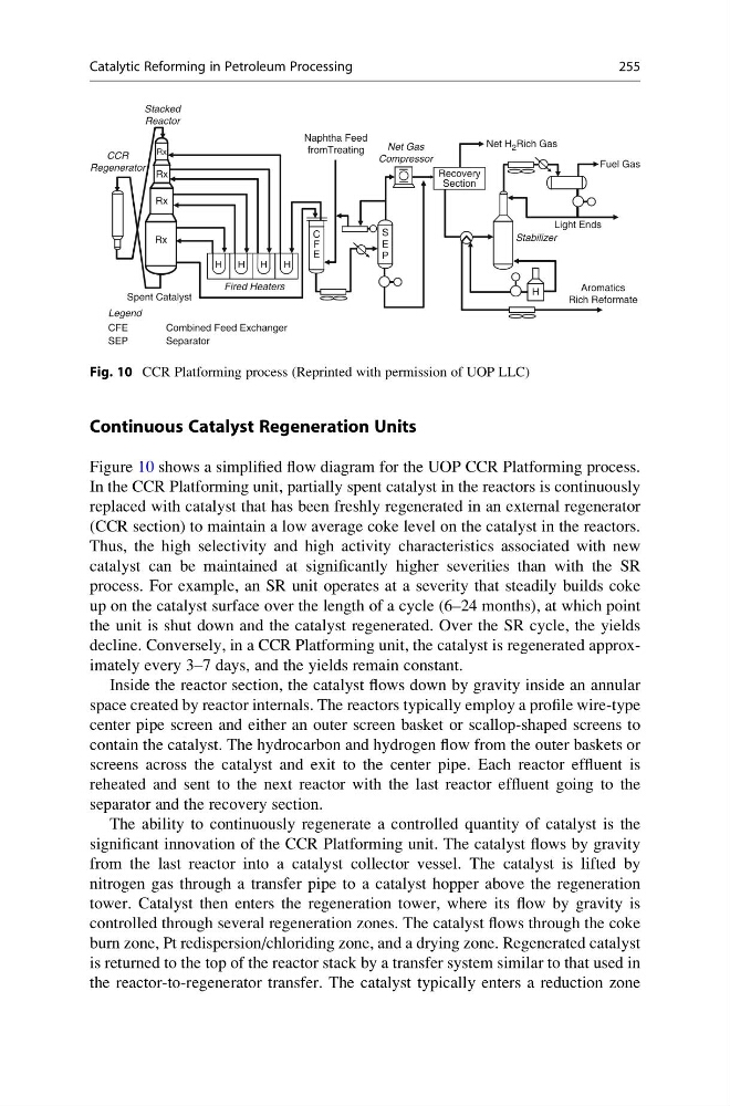
Figure 10 shows a simplified flow diagram for the UOP CCR Platforming process.
In the CCR Platforming unit, partially spent catalyst in the reactors is continuously
replaced with catalyst that has been freshly regenerated in an external regenerator
(CCR section) to maintain a low average coke level on the catalyst in the reactors.
Thus, the high selectivity and high activity characteristics associated with new
catalyst can be maintained at significantly higher severities than with the SR
process. For example, an SR unit operates at a severity that steadily builds coke
up on the catalyst surface over the length of a cycle (6–24 months), at which point
the unit is shut down and the catalyst regenerated. Over the SR cycle, the yields
decline. Conversely, in a CCR Platforming unit, the catalyst is regenerated approximately every 3–7 days, and the yields remain constant.
Inside the reactor section, the catalyst flows down by gravity inside an annular
space created by reactor internals. The reactors typically employ a profile wire-type
center pipe screen and either an outer screen basket or scallop-shaped screens to
contain the catalyst. The hydrocarbon and hydrogen flow from the outer baskets or
screens across the catalyst and exit to the center pipe. Each reactor effluent is
reheated and sent to the next reactor with the last reactor effluent going to the
separator and the recovery section.
The ability to continuously regenerate a controlled quantity of catalyst is the
significant innovation of the CCR Platforming unit. The catalyst flows by gravity
from the last reactor into a catalyst collector vessel. The catalyst is lifted by
nitrogen gas through a transfer pipe to a catalyst hopper above the regeneration
tower. Catalyst then enters the regeneration tower, where its flow by gravity is
controlled through several regeneration zones. The catalyst flows through the coke
burn zone, Pt redispersion/chloriding zone, and a drying zone. Regenerated catalyst
is returned to the top of the reactor stack by a transfer system similar to that used in
the reactor-to-regenerator transfer. The catalyst typically enters a reduction zone
Rx
Rx
Rx
Rx
Rx
Rx
Rx
Rx
H
H
H
H
C
F
E
H
H
S
E
P
S
E
P
Stabilizer
Recovery
Section
Net H 2 Rich Gas
Net Gas
Compressor
Fuel Gas
Light Ends
Aromatics
Rich Reformate
Naphtha Feed
fromTreating
Stacked
Reactor
Legend
CFE
Combined Feed Exchanger
Separator
SEP
Fired Heaters
Spent Catalyst
CCR
Regenerator
Fig. 10 CCR Platforming process (Reprinted with permission of UOP LLC)
Catalytic Reforming in Petroleum Processing
255
Figure 10 shows a simplified flow diagram for the UOP CCR Platforming process.
In the CCR Platforming unit, partially spent catalyst in the reactors is continuously
replaced with catalyst that has been freshly regenerated in an external regenerator
(CCR section) to maintain a low average coke level on the catalyst in the reactors.
Thus, the high selectivity and high activity characteristics associated with new
catalyst can be maintained at significantly higher severities than with the SR
process. For example, an SR unit operates at a severity that steadily builds coke
up on the catalyst surface over the length of a cycle (6–24 months), at which point
the unit is shut down and the catalyst regenerated. Over the SR cycle, the yields
decline. Conversely, in a CCR Platforming unit, the catalyst is regenerated approximately every 3–7 days, and the yields remain constant.
Inside the reactor section, the catalyst flows down by gravity inside an annular
space created by reactor internals. The reactors typically employ a profile wire-type
center pipe screen and either an outer screen basket or scallop-shaped screens to
contain the catalyst. The hydrocarbon and hydrogen flow from the outer baskets or
screens across the catalyst and exit to the center pipe. Each reactor effluent is
reheated and sent to the next reactor with the last reactor effluent going to the
separator and the recovery section.
The ability to continuously regenerate a controlled quantity of catalyst is the
significant innovation of the CCR Platforming unit. The catalyst flows by gravity
from the last reactor into a catalyst collector vessel. The catalyst is lifted by
nitrogen gas through a transfer pipe to a catalyst hopper above the regeneration
tower. Catalyst then enters the regeneration tower, where its flow by gravity is
controlled through several regeneration zones. The catalyst flows through the coke
burn zone, Pt redispersion/chloriding zone, and a drying zone. Regenerated catalyst
is returned to the top of the reactor stack by a transfer system similar to that used in
the reactor-to-regenerator transfer. The catalyst typically enters a reduction zone
Rx
Rx
Rx
Rx
Rx
Rx
Rx
Rx
H
H
H
H
C
F
E
H
H
S
E
P
S
E
P
Stabilizer
Recovery
Section
Net H 2 Rich Gas
Net Gas
Compressor
Fuel Gas
Light Ends
Aromatics
Rich Reformate
Naphtha Feed
fromTreating
Stacked
Reactor
Legend
CFE
Combined Feed Exchanger
Separator
SEP
Fired Heaters
Spent Catalyst
CCR
Regenerator
Fig. 10 CCR Platforming process (Reprinted with permission of UOP LLC)
Catalytic Reforming in Petroleum Processing
255