

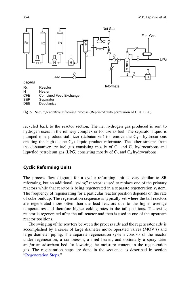
recycled back to the reactor section. The net hydrogen gas produced is sent to
hydrogen users in the refinery complex or for use as fuel. The separator liquid is
pumped to a product stabilizer (debutanizer) to remove the C 4 À hydrocarbons
creating the high-octane C 5 + liquid product reformate. The other streams from
the debutanizer are fuel gas consisting mostly of C 1 and C 2 hydrocarbons and
liquefied petroleum gas (LPG) consisting mostly of C 3 and C 4 hydrocarbons.
Cyclic Reforming Units
The process flow diagram for a cyclic reforming unit is very similar to SR
reforming, but an additional “swing” reactor is used to replace one of the primary
reactors while that reactor is being regenerated in a separate regeneration system.
The frequency of regenerating for a particular reactor position depends on the rate
of coke buildup. The regeneration sequence is typically set where the tail reactors
are regenerated more often than the lead reactors due to the higher average
temperatures and therefore higher coking rates in the tail positions. The swing
reactor is regenerated after the tail reactor and then is used in one of the upstream
reactor positions.
The swinging of the reactors between the process side and the regenerator side is
accomplished by a series of large diameter motor operated valves (MOV’s) and
large diameter piping. The separate regeneration system consists of the reactor
under regeneration, a compressor, a fired heater, and optionally a spray drier
and/or an adsorbent bed for lowering the moisture content in the regeneration
gas. The regeneration steps are done in the sequence as described in section
“Regeneration Steps.”
Legend
Rx
Reactor
H
Heater
CFE
Combined Feed Exchanger
SEP
Separator
DEB
Debutanizer
Net Gas
Fuel Gas
LPG
Reformate
Feed
H H H
H H H
H H H
H H H
Rx Rx
Rx Rx
Rx Rx
C
F
E
S
E
P
D
E
B
Fig. 9 Semiregenerative reforming process (Reprinted with permission of UOP LLC)
254
M.P. Lapinski et al.
hydrogen users in the refinery complex or for use as fuel. The separator liquid is
pumped to a product stabilizer (debutanizer) to remove the C 4 À hydrocarbons
creating the high-octane C 5 + liquid product reformate. The other streams from
the debutanizer are fuel gas consisting mostly of C 1 and C 2 hydrocarbons and
liquefied petroleum gas (LPG) consisting mostly of C 3 and C 4 hydrocarbons.
Cyclic Reforming Units
The process flow diagram for a cyclic reforming unit is very similar to SR
reforming, but an additional “swing” reactor is used to replace one of the primary
reactors while that reactor is being regenerated in a separate regeneration system.
The frequency of regenerating for a particular reactor position depends on the rate
of coke buildup. The regeneration sequence is typically set where the tail reactors
are regenerated more often than the lead reactors due to the higher average
temperatures and therefore higher coking rates in the tail positions. The swing
reactor is regenerated after the tail reactor and then is used in one of the upstream
reactor positions.
The swinging of the reactors between the process side and the regenerator side is
accomplished by a series of large diameter motor operated valves (MOV’s) and
large diameter piping. The separate regeneration system consists of the reactor
under regeneration, a compressor, a fired heater, and optionally a spray drier
and/or an adsorbent bed for lowering the moisture content in the regeneration
gas. The regeneration steps are done in the sequence as described in section
“Regeneration Steps.”
Legend
Rx
Reactor
H
Heater
CFE
Combined Feed Exchanger
SEP
Separator
DEB
Debutanizer
Net Gas
Fuel Gas
LPG
Reformate
Feed
H H H
H H H
H H H
H H H
Rx Rx
Rx Rx
Rx Rx
C
F
E
S
E
P
D
E
B
Fig. 9 Semiregenerative reforming process (Reprinted with permission of UOP LLC)
254
M.P. Lapinski et al.