

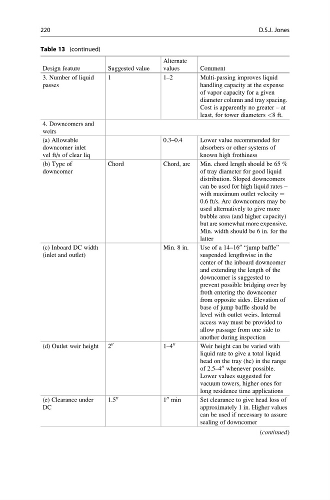
Table 13 (continued)
Design feature
Suggested value
Alternate
values
Comment
3. Number of liquid
passes
1
1–2
Multi-passing improves liquid
handling capacity at the expense
of vapor capacity for a given
diameter column and tray spacing.
Cost is apparently no greater – at
least, for tower diameters <8 ft.
4. Downcomers and
weirs
(a) Allowable
downcomer inlet
vel ft/s of clear liq
0.3–0.4
Lower value recommended for
absorbers or other systems of
known high frothiness
(b) Type of
downcomer
Chord
Chord, arc
Min. chord length should be 65 %
of tray diameter for good liquid
distribution. Sloped downcomers
can be used for high liquid rates –
with maximum outlet velocity =
0.6 ft/s. Arc downcomers may be
used alternatively to give more
bubble area (and higher capacity)
but are somewhat more expensive.
Min. width should be 6 in. for the
latter
(c) Inboard DC width
(inlet and outlet)
Min. 8 in.
Use of a 14–16
00 “jump baffle”
suspended lengthwise in the
center of the inboard downcomer
and extending the length of the
downcomer is suggested to
prevent possible bridging over by
froth entering the downcomer
from opposite sides. Elevation of
base of jump baffle should be
level with outlet weirs. Internal
access way must be provided to
allow passage from one side to
another during inspection
(d) Outlet weir height 2
00
1–4
00
Weir height can be varied with
liquid rate to give a total liquid
head on the tray (hc) in the range
of 2.5–4
00 whenever possible.
Lower values suggested for
vacuum towers, higher ones for
long residence time applications
(e) Clearance under
DC
1.5
00
1
00 min
Set clearance to give head loss of
approximately 1 in. Higher values
can be used if necessary to assure
sealing of downcomer
(continued)
220
D.S.J. Jones
Design feature
Suggested value
Alternate
values
Comment
3. Number of liquid
passes
1
1–2
Multi-passing improves liquid
handling capacity at the expense
of vapor capacity for a given
diameter column and tray spacing.
Cost is apparently no greater – at
least, for tower diameters <8 ft.
4. Downcomers and
weirs
(a) Allowable
downcomer inlet
vel ft/s of clear liq
0.3–0.4
Lower value recommended for
absorbers or other systems of
known high frothiness
(b) Type of
downcomer
Chord
Chord, arc
Min. chord length should be 65 %
of tray diameter for good liquid
distribution. Sloped downcomers
can be used for high liquid rates –
with maximum outlet velocity =
0.6 ft/s. Arc downcomers may be
used alternatively to give more
bubble area (and higher capacity)
but are somewhat more expensive.
Min. width should be 6 in. for the
latter
(c) Inboard DC width
(inlet and outlet)
Min. 8 in.
Use of a 14–16
00 “jump baffle”
suspended lengthwise in the
center of the inboard downcomer
and extending the length of the
downcomer is suggested to
prevent possible bridging over by
froth entering the downcomer
from opposite sides. Elevation of
base of jump baffle should be
level with outlet weirs. Internal
access way must be provided to
allow passage from one side to
another during inspection
(d) Outlet weir height 2
00
1–4
00
Weir height can be varied with
liquid rate to give a total liquid
head on the tray (hc) in the range
of 2.5–4
00 whenever possible.
Lower values suggested for
vacuum towers, higher ones for
long residence time applications
(e) Clearance under
DC
1.5
00
1
00 min
Set clearance to give head loss of
approximately 1 in. Higher values
can be used if necessary to assure
sealing of downcomer
(continued)
220
D.S.J. Jones