

ρ v = Density of vapor in lb/cuft at section conditions of temperature and
pressure.
ρ l = Density of liquid in lb/cuft at section conditions.
Step 5. Calculate the actual vapor velocity required by multiplying the calculated
velocity at flood by percent of flood permissible if this is to be a new design. The
design cross-sectional area of the tower is then the calculated vapor load in cuft/s
divided by the actual vapor velocity. If the unit is existing, divide the vapor
loading in cuft/s by the cross-sectional area of the tower to arrive at the actual
vapor velocity in ft/s. The existing unit operation as a percent of flood will be the
actual velocity divided by the calculated flood velocity times 100.
Step 6. Estimate the HETP (height equivalent to a theoretical tray) as being between
1.5 and 2.0 ft. Use the higher figure for vapor percent of flood 50–95 % or higher
and the lower value for vapor flood below 50 %.
Step 7. Calculate the height of the packed section required for heat transfer using the
quantity of heat to be transferred as being the pumparound duty in Btu/h. Then
treat the section above the pumparound drawoff as a simple heat exchanger. Use
the liquid flow to this section and the pumparound flow as calculated in the
previous section (as part of the tower liquid load). The inlet temperature to the
section can be taken as that for the pumparound liquid flow into the tower and the
temperature out of the section as the pumparound drawoff temperature.
200
30 40 50 60 80 100
Millimeters of Mercury
200 300 400 500 760 20
30 40 50 60 80 100
200 300 400 600 800 1000
500
600
150
100
50
0
Temperature °F
−50
−100
0.5
0.6 0.81.0
2
3 4 5 6 8 10 14.7 20
Pressure
lbs/in
2
abs
lbs/in
2 abs
30 40 50 60 80 100
200 300 400 500 600 800 1000
η − O C T A N E
η − H E P T A N E
η − P E N T A N E
η
−
B U T A N E
1 5 0
B U T A N E
P R
O
P A N
E
P R
O
P Y L E N
E
E T H A N E E T H Y L E N E
1 5 0
P E N T A N E
η − H E X A N E
T O L U E N E
B E N Z E N E
ATMOSPHERIC PRESSURE
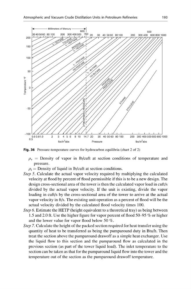
Fig. 36 Pressure-temperature curves for hydrocarbon equilibria (chart 2 of 2)
Atmospheric and Vacuum Crude Distillation Units in Petroleum Refineries
193
pressure.
ρ l = Density of liquid in lb/cuft at section conditions.
Step 5. Calculate the actual vapor velocity required by multiplying the calculated
velocity at flood by percent of flood permissible if this is to be a new design. The
design cross-sectional area of the tower is then the calculated vapor load in cuft/s
divided by the actual vapor velocity. If the unit is existing, divide the vapor
loading in cuft/s by the cross-sectional area of the tower to arrive at the actual
vapor velocity in ft/s. The existing unit operation as a percent of flood will be the
actual velocity divided by the calculated flood velocity times 100.
Step 6. Estimate the HETP (height equivalent to a theoretical tray) as being between
1.5 and 2.0 ft. Use the higher figure for vapor percent of flood 50–95 % or higher
and the lower value for vapor flood below 50 %.
Step 7. Calculate the height of the packed section required for heat transfer using the
quantity of heat to be transferred as being the pumparound duty in Btu/h. Then
treat the section above the pumparound drawoff as a simple heat exchanger. Use
the liquid flow to this section and the pumparound flow as calculated in the
previous section (as part of the tower liquid load). The inlet temperature to the
section can be taken as that for the pumparound liquid flow into the tower and the
temperature out of the section as the pumparound drawoff temperature.
200
30 40 50 60 80 100
Millimeters of Mercury
200 300 400 500 760 20
30 40 50 60 80 100
200 300 400 600 800 1000
500
600
150
100
50
0
Temperature °F
−50
−100
0.5
0.6 0.81.0
2
3 4 5 6 8 10 14.7 20
Pressure
lbs/in
2
abs
lbs/in
2 abs
30 40 50 60 80 100
200 300 400 500 600 800 1000
η − O C T A N E
η − H E P T A N E
η − P E N T A N E
η
−
B U T A N E
1 5 0
B U T A N E
P R
O
P A N
E
P R
O
P Y L E N
E
E T H A N E E T H Y L E N E
1 5 0
P E N T A N E
η − H E X A N E
T O L U E N E
B E N Z E N E
ATMOSPHERIC PRESSURE
Fig. 36 Pressure-temperature curves for hydrocarbon equilibria (chart 2 of 2)
Atmospheric and Vacuum Crude Distillation Units in Petroleum Refineries
193