

published work titled Elements of Chemical Process Engineering. The following
are the calculation steps used for this quick general packed section evaluation:
Step 1. Determine the liquid and vapor flows across the section to be evaluated.
As calculated in the previous section, “Determine Pumparound and Internal
Flows for Vacuum Towers.”
Step 2. If the unit is existing and this calculation is to determine tower performance,
then use manufacturer’s drawings for tower details such as dimensions of the
packed section.
Step 3. Calculate the liquid and vapor loads in terms of actual cubic feet per second
for vapor and cubic feet per hour per square foot of tower for the liquid. All these
will be at tray conditions of temperature and pressure.
Step 4. Using the liquid load as calculated in step 3, read off the value for capacity
factor “K” from Fig. 32.
Calculate the linear velocity of the vapor at flood from the expression
K ¼ V f
ffiffiffiffiffiffiffiffiffiffiffiffiffiffiffiffiffiffiffiffiffiffiffiffi ffi
ρ v = ρ l À ρ v
ð
Þ
p
(15)
where
V f = Vapor velocity at flood in ft/s.
30
1200
1100
1000
900
800
700
600
550
500
450
400
350
300
250
Temperature
°F
ATMOSPHERIC PRESSURE
ATMOSPHERIC PRESSURE
ATMOSPHERIC PRESSURE
200
150
100
60
0.5
0.6 0.8 1.0
2
3
4
lbs/in 2 abs
lbs/in 2 abs
lbs/in 2 abs
5 6 8 10 14.7
O C T A N E
T O L U E N C E
B E N Z E N E
1 5 0
P E N T A N E
1 5 0
B U T A N E
P R
O
P A N
E
P R O
P Y L E N E
E T H A N E
η - H E P T A N E
η - H E X A N E
η
- P E N T A N E
η
- B U T A N E
20
30 40 50
Pressure
60 80 100
200 300 400
600
500
800 1000
2000
40 5060 80 100
200
Millimetres of mercury
300 400 600
500
760 20
30 40 50 60 80 100
200
300 400
600
500
800 1000
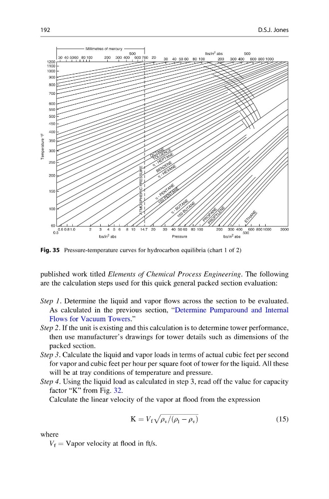
Fig. 35 Pressure-temperature curves for hydrocarbon equilibria (chart 1 of 2)
192
D.S.J. Jones
are the calculation steps used for this quick general packed section evaluation:
Step 1. Determine the liquid and vapor flows across the section to be evaluated.
As calculated in the previous section, “Determine Pumparound and Internal
Flows for Vacuum Towers.”
Step 2. If the unit is existing and this calculation is to determine tower performance,
then use manufacturer’s drawings for tower details such as dimensions of the
packed section.
Step 3. Calculate the liquid and vapor loads in terms of actual cubic feet per second
for vapor and cubic feet per hour per square foot of tower for the liquid. All these
will be at tray conditions of temperature and pressure.
Step 4. Using the liquid load as calculated in step 3, read off the value for capacity
factor “K” from Fig. 32.
Calculate the linear velocity of the vapor at flood from the expression
K ¼ V f
ffiffiffiffiffiffiffiffiffiffiffiffiffiffiffiffiffiffiffiffiffiffiffiffi ffi
ρ v = ρ l À ρ v
ð
Þ
p
(15)
where
V f = Vapor velocity at flood in ft/s.
30
1200
1100
1000
900
800
700
600
550
500
450
400
350
300
250
Temperature
°F
ATMOSPHERIC PRESSURE
ATMOSPHERIC PRESSURE
ATMOSPHERIC PRESSURE
200
150
100
60
0.5
0.6 0.8 1.0
2
3
4
lbs/in 2 abs
lbs/in 2 abs
lbs/in 2 abs
5 6 8 10 14.7
O C T A N E
T O L U E N C E
B E N Z E N E
1 5 0
P E N T A N E
1 5 0
B U T A N E
P R
O
P A N
E
P R O
P Y L E N E
E T H A N E
η - H E P T A N E
η - H E X A N E
η
- P E N T A N E
η
- B U T A N E
20
30 40 50
Pressure
60 80 100
200 300 400
600
500
800 1000
2000
40 5060 80 100
200
Millimetres of mercury
300 400 600
500
760 20
30 40 50 60 80 100
200
300 400
600
500
800 1000
Fig. 35 Pressure-temperature curves for hydrocarbon equilibria (chart 1 of 2)
192
D.S.J. Jones