

where
A s = Total tray area in sqft.
A dc = Inlet and outlet down comer areas in sqft.
A w = Waste area (about 20 % of A b ).
A b = Bubble area.
A s = A b + A w + A dc .
Use Appendix 4 (relationship of chord height, area, and length) as applicable.
Calculate the Overall Tower Height
Using the vapor and liquid calculations, check and fix the number of trays used to
meet the tower’s fractionation requirements. Then check the tray spacing.
For normal fractionation a 24 in. tray spacing is acceptable. For drawoff trays
with pumparound, the section should be checked for high downcomer filling (i.e., in
excess of 50 %). Trays in this section often require bigger tray spacing, usually
30 in. Calculate the tower height allocated to the trays. Allow 6 f. between top tray
and the top tangent line of the vessel to allow space for the reflux distributor and
good liquid/vapor separation.
The space required for the flash zone (between the bottom fractionating tray and
the top residue stripper tray) is usually 10–14 f. depending on throughput and the
swirl size. The hot well below the bottom residue stripping tray should be sized to
1300
1100
Sieve and valve
flood line
Sieve and valve
tray design
Bubble cap
trays (max)
900
700
K
500
300
100
10
15
20
25
Tray Spacing Ins
30
35
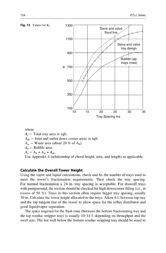
Fig. 13 Values for K f
154
D.S.J. Jones
A s = Total tray area in sqft.
A dc = Inlet and outlet down comer areas in sqft.
A w = Waste area (about 20 % of A b ).
A b = Bubble area.
A s = A b + A w + A dc .
Use Appendix 4 (relationship of chord height, area, and length) as applicable.
Calculate the Overall Tower Height
Using the vapor and liquid calculations, check and fix the number of trays used to
meet the tower’s fractionation requirements. Then check the tray spacing.
For normal fractionation a 24 in. tray spacing is acceptable. For drawoff trays
with pumparound, the section should be checked for high downcomer filling (i.e., in
excess of 50 %). Trays in this section often require bigger tray spacing, usually
30 in. Calculate the tower height allocated to the trays. Allow 6 f. between top tray
and the top tangent line of the vessel to allow space for the reflux distributor and
good liquid/vapor separation.
The space required for the flash zone (between the bottom fractionating tray and
the top residue stripper tray) is usually 10–14 f. depending on throughput and the
swirl size. The hot well below the bottom residue stripping tray should be sized to
1300
1100
Sieve and valve
flood line
Sieve and valve
tray design
Bubble cap
trays (max)
900
700
K
500
300
100
10
15
20
25
Tray Spacing Ins
30
35
Fig. 13 Values for K f
154
D.S.J. Jones