

The calculation procedure and data described below will give a good estimate of
the tower diameter. For design purposes however the tray fabricator or designer
data and procedure should be used. Trays are usually proprietary items covered by
patents, and their performance therefore is subject to guarantees.
A calculation procedure to estimate the tower diameter is as follows:
Step 1. Summarize the liquid traffic through the tray.
Step 2. Select the type of tray that is to be considered for the design (in the case of an
existing unit, refer to the fabricator’s drawings). Valve and sieve trays have
reasonable similarity in their major characteristics. Bubble cap trays are seldom
used these days. A table of the valve tray characteristics is given in Appendix 3
of this chapter.
Step 3. Compute the liquid loading on the tray being checked for size. This will
include all the liquid entering the tray. For example, on a side stream drawoff
tray under a pumparound section, it will include:
• The side stream feed to the stripper
• The pumparound liquid
• The liquid overflow from the tray
This loading should be in cubic feet per second (CFS).
Step 4. In the case of a new design, set the downcomer area in accordance with
Appendix 4 of this chapter. For an existing tray use the fabricator’s drawings.
Calculate the linear velocity of the liquid in ft/s. For good design this velocity
should not exceed 0.6 ft/s at the downcomer outlet. Tray spacing should be such
that the liquid level in the downcomer should not exceed 50 % of the tray
spacing. To meet these criteria, tray spacing on these critical liquid loading
trays may be higher than the remaining tray spacing in the tower.
Step 5. Summarize the vapor traffic to the critical tray under examination. This
should be in lb/h and mol/h. The vapor should be the total vapor as used to
calculate the tray overflow.
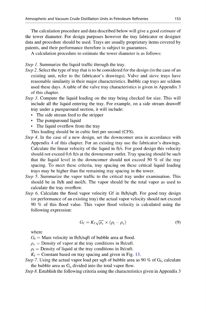
Step 6. Calculate the flood vapor velocity Gf in lb/h/sqft. For good tray design
(or performance of an existing tray) the actual vapor velocity should not exceed
90 % of this flood value. This vapor flood velocity is calculated using the
following expression:
G f ¼ K f
ffiffiffiffi ffi
ρ v
p  ρ l À ρ v
ð
Þ
(9)
where
G f = Mass velocity in lb/h/sqft of bubble area at flood.
ρ v = Density of vapor at the tray conditions in lb/cuft.
ρ l = Density of liquid at the tray conditions in lb/cuft.
K f = Constant based on tray spacing and given in Fig. 13.
Step 7. Using the actual vapor load per sqft of bubble area as 90 % of G f , calculate
the bubble area as G a divided into the total vapor flow.
Step 8. Establish the following criteria using the characteristics given in Appendix 3
Atmospheric and Vacuum Crude Distillation Units in Petroleum Refineries
153
the tower diameter. For design purposes however the tray fabricator or designer
data and procedure should be used. Trays are usually proprietary items covered by
patents, and their performance therefore is subject to guarantees.
A calculation procedure to estimate the tower diameter is as follows:
Step 1. Summarize the liquid traffic through the tray.
Step 2. Select the type of tray that is to be considered for the design (in the case of an
existing unit, refer to the fabricator’s drawings). Valve and sieve trays have
reasonable similarity in their major characteristics. Bubble cap trays are seldom
used these days. A table of the valve tray characteristics is given in Appendix 3
of this chapter.
Step 3. Compute the liquid loading on the tray being checked for size. This will
include all the liquid entering the tray. For example, on a side stream drawoff
tray under a pumparound section, it will include:
• The side stream feed to the stripper
• The pumparound liquid
• The liquid overflow from the tray
This loading should be in cubic feet per second (CFS).
Step 4. In the case of a new design, set the downcomer area in accordance with
Appendix 4 of this chapter. For an existing tray use the fabricator’s drawings.
Calculate the linear velocity of the liquid in ft/s. For good design this velocity
should not exceed 0.6 ft/s at the downcomer outlet. Tray spacing should be such
that the liquid level in the downcomer should not exceed 50 % of the tray
spacing. To meet these criteria, tray spacing on these critical liquid loading
trays may be higher than the remaining tray spacing in the tower.
Step 5. Summarize the vapor traffic to the critical tray under examination. This
should be in lb/h and mol/h. The vapor should be the total vapor as used to
calculate the tray overflow.
Step 6. Calculate the flood vapor velocity Gf in lb/h/sqft. For good tray design
(or performance of an existing tray) the actual vapor velocity should not exceed
90 % of this flood value. This vapor flood velocity is calculated using the
following expression:
G f ¼ K f
ffiffiffiffi ffi
ρ v
p  ρ l À ρ v
ð
Þ
(9)
where
G f = Mass velocity in lb/h/sqft of bubble area at flood.
ρ v = Density of vapor at the tray conditions in lb/cuft.
ρ l = Density of liquid at the tray conditions in lb/cuft.
K f = Constant based on tray spacing and given in Fig. 13.
Step 7. Using the actual vapor load per sqft of bubble area as 90 % of G f , calculate
the bubble area as G a divided into the total vapor flow.
Step 8. Establish the following criteria using the characteristics given in Appendix 3
Atmospheric and Vacuum Crude Distillation Units in Petroleum Refineries
153