

stripper which enters the vapor space above the drawoff tray.) The amount of
stripping steam recommended is given in Fig. 10.
Step 2. Fix the total pressure on the tray taking the estimated tower top pressure and
each tray pressure drop above the drawoff tray (see the previous paragraphs on
flash zone and overhead system). Estimate the position of the drawoff tray. As a
guide the following rule of thumb can be used. With tray 1 as the top tray in the
column:
Kero drawoff
Tray 12
Light gas oil
Tray 22
Heavy gas oil
Tray 32
There are usually 40 fractionating trays (i.e., trays above the flash zone) and four
bottom stripping trays in conventional distillation towers. These amounts will be
checked later using the relationship of reflux to tray ratio for fractionation
criteria.
Step 3. Calculate the FRL (flash reference line) for the drawoff TBP cut. In doing
this, use the TBP cut, not the TBP end points. This calculation has been
described under the section on the flash zone. Establish its IBP at atmospheric
pressure. This will be the 0 %vol temperature on the FRL.
Step 4. Predict the amount of overflow that will leave the drawoff tray as a liquid
reflux to the tray below. Again this will be checked by the relationship of trays
240
REFERENCE:
PACKIE, TRANS.AI.CH.S. 27.51 (PB54)
• IBP OF THE FLASH CURVE BASED ON
TBPC OF THE CRUDE TAKEN AT PARTIAL
PRESSURE OF SIDEOUT
220
200
180
160
140
120
100
80
60
40
20
The cretical sidedraw liquid temperature- Actual
sidedraw temperature °F
0
100
200
300
400
0% Point of cut on atmospheric TBPC of crude °F
500
600
NOTE
USE ONLY WITH PACKIE METHOD
700
800
900
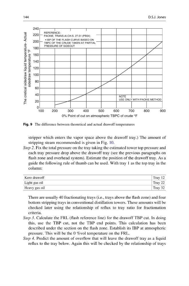
Fig. 9 The difference between theoretical and actual drawoff temperatures
144
D.S.J. Jones
stripping steam recommended is given in Fig. 10.
Step 2. Fix the total pressure on the tray taking the estimated tower top pressure and
each tray pressure drop above the drawoff tray (see the previous paragraphs on
flash zone and overhead system). Estimate the position of the drawoff tray. As a
guide the following rule of thumb can be used. With tray 1 as the top tray in the
column:
Kero drawoff
Tray 12
Light gas oil
Tray 22
Heavy gas oil
Tray 32
There are usually 40 fractionating trays (i.e., trays above the flash zone) and four
bottom stripping trays in conventional distillation towers. These amounts will be
checked later using the relationship of reflux to tray ratio for fractionation
criteria.
Step 3. Calculate the FRL (flash reference line) for the drawoff TBP cut. In doing
this, use the TBP cut, not the TBP end points. This calculation has been
described under the section on the flash zone. Establish its IBP at atmospheric
pressure. This will be the 0 %vol temperature on the FRL.
Step 4. Predict the amount of overflow that will leave the drawoff tray as a liquid
reflux to the tray below. Again this will be checked by the relationship of trays
240
REFERENCE:
PACKIE, TRANS.AI.CH.S. 27.51 (PB54)
• IBP OF THE FLASH CURVE BASED ON
TBPC OF THE CRUDE TAKEN AT PARTIAL
PRESSURE OF SIDEOUT
220
200
180
160
140
120
100
80
60
40
20
The cretical sidedraw liquid temperature- Actual
sidedraw temperature °F
0
100
200
300
400
0% Point of cut on atmospheric TBPC of crude °F
500
600
NOTE
USE ONLY WITH PACKIE METHOD
700
800
900
Fig. 9 The difference between theoretical and actual drawoff temperatures
144
D.S.J. Jones