

Configuration 1
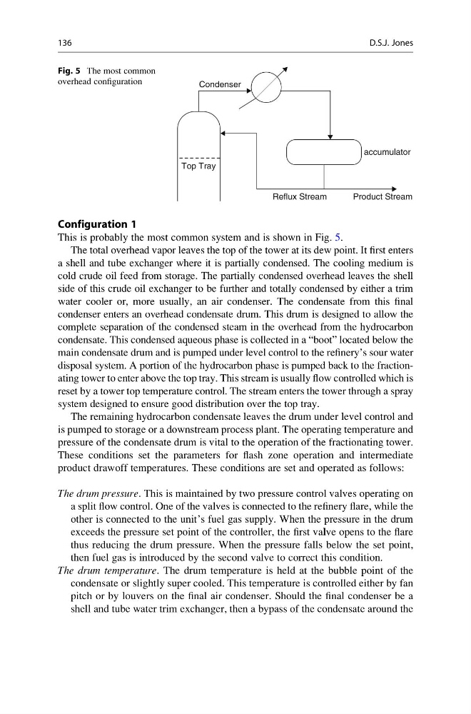
This is probably the most common system and is shown in Fig. 5.
The total overhead vapor leaves the top of the tower at its dew point. It first enters
a shell and tube exchanger where it is partially condensed. The cooling medium is
cold crude oil feed from storage. The partially condensed overhead leaves the shell
side of this crude oil exchanger to be further and totally condensed by either a trim
water cooler or, more usually, an air condenser. The condensate from this final
condenser enters an overhead condensate drum. This drum is designed to allow the
complete separation of the condensed steam in the overhead from the hydrocarbon
condensate. This condensed aqueous phase is collected in a “boot” located below the
main condensate drum and is pumped under level control to the refinery’s sour water
disposal system. A portion of the hydrocarbon phase is pumped back to the fractionating tower to enter above the top tray. This stream is usually flow controlled which is
reset by a tower top temperature control. The stream enters the tower through a spray
system designed to ensure good distribution over the top tray.
The remaining hydrocarbon condensate leaves the drum under level control and
is pumped to storage or a downstream process plant. The operating temperature and
pressure of the condensate drum is vital to the operation of the fractionating tower.
These conditions set the parameters for flash zone operation and intermediate
product drawoff temperatures. These conditions are set and operated as follows:
The drum pressure. This is maintained by two pressure control valves operating on
a split flow control. One of the valves is connected to the refinery flare, while the
other is connected to the unit’s fuel gas supply. When the pressure in the drum
exceeds the pressure set point of the controller, the first valve opens to the flare
thus reducing the drum pressure. When the pressure falls below the set point,
then fuel gas is introduced by the second valve to correct this condition.
The drum temperature. The drum temperature is held at the bubble point of the
condensate or slightly super cooled. This temperature is controlled either by fan
pitch or by louvers on the final air condenser. Should the final condenser be a
shell and tube water trim exchanger, then a bypass of the condensate around the
Condenser
accumulator
Reflux Stream
Top Tray
Product Stream
Fig. 5 The most common
overhead configuration
136
D.S.J. Jones
This is probably the most common system and is shown in Fig. 5.
The total overhead vapor leaves the top of the tower at its dew point. It first enters
a shell and tube exchanger where it is partially condensed. The cooling medium is
cold crude oil feed from storage. The partially condensed overhead leaves the shell
side of this crude oil exchanger to be further and totally condensed by either a trim
water cooler or, more usually, an air condenser. The condensate from this final
condenser enters an overhead condensate drum. This drum is designed to allow the
complete separation of the condensed steam in the overhead from the hydrocarbon
condensate. This condensed aqueous phase is collected in a “boot” located below the
main condensate drum and is pumped under level control to the refinery’s sour water
disposal system. A portion of the hydrocarbon phase is pumped back to the fractionating tower to enter above the top tray. This stream is usually flow controlled which is
reset by a tower top temperature control. The stream enters the tower through a spray
system designed to ensure good distribution over the top tray.
The remaining hydrocarbon condensate leaves the drum under level control and
is pumped to storage or a downstream process plant. The operating temperature and
pressure of the condensate drum is vital to the operation of the fractionating tower.
These conditions set the parameters for flash zone operation and intermediate
product drawoff temperatures. These conditions are set and operated as follows:
The drum pressure. This is maintained by two pressure control valves operating on
a split flow control. One of the valves is connected to the refinery flare, while the
other is connected to the unit’s fuel gas supply. When the pressure in the drum
exceeds the pressure set point of the controller, the first valve opens to the flare
thus reducing the drum pressure. When the pressure falls below the set point,
then fuel gas is introduced by the second valve to correct this condition.
The drum temperature. The drum temperature is held at the bubble point of the
condensate or slightly super cooled. This temperature is controlled either by fan
pitch or by louvers on the final air condenser. Should the final condenser be a
shell and tube water trim exchanger, then a bypass of the condensate around the
Condenser
accumulator
Reflux Stream
Top Tray
Product Stream
Fig. 5 The most common
overhead configuration
136
D.S.J. Jones