

The property curves are developed from pilot plant runs on a similar feed
stock. These are based on total product % volume. Refer to Tables 20 and 21;
Figs. 9, 10, and 11.
The gas to 380
F stream will be routed as the overhead distillate from the
thermal cracker syncrude fractionator to the naphtha hydrotreater and the saturated
light ends unit.
The gas oil stream will be routed to the straight run diesel hydrotreater.
The cracked residue will be routed directly to the fuel oil pool.
The HyGO hydrotreater on cat cracker (FCCU) feed operation. The feed to the
heavy gas oil hydrotreater will be the HVGO stream from the vacuum distillation unit
(VDU) to meet the feed requirements of a FCCU. This hydrotreater will operate on a
blocked operation with the LVGO. That is, it will operate so many days processing
HVGO and the remainder of the “stream” year processing LVGO.
Details of the HVGO operation are in Figs. 9, 10, and 11, with the following
specifics:
Feed to the hydrotreater = 9,275 BPCD
SG at 60 = 0.9218
Pounds/gal = 7.678
Pounds/CD = 2,990,965
% wt sulfur = 3.10
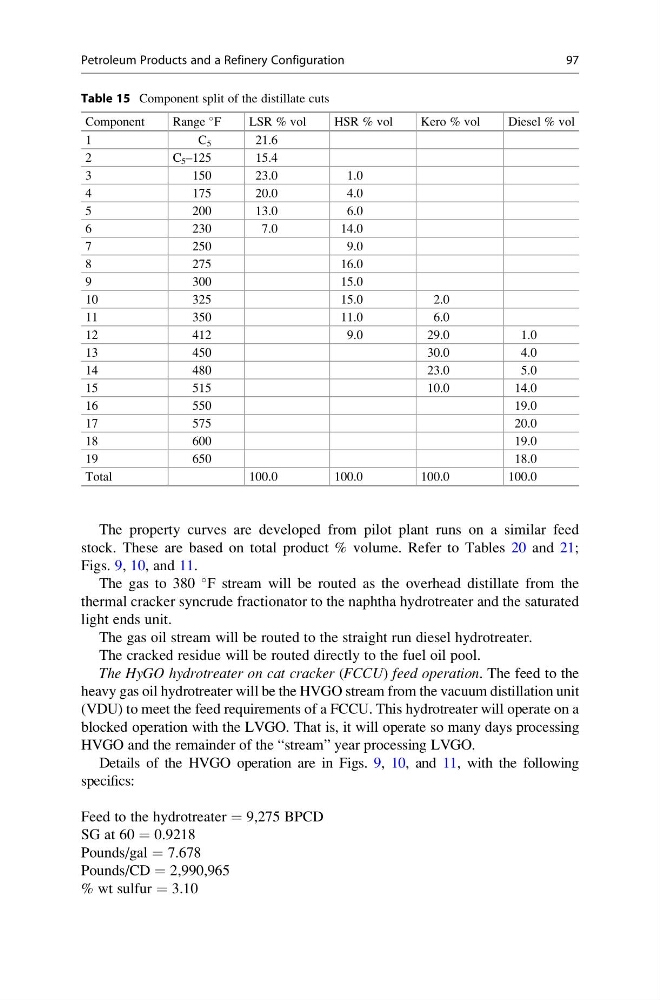
Table 15 Component split of the distillate cuts
Component
Range
F
LSR % vol
HSR % vol
Kero % vol
Diesel % vol
1
C 5
21.6
2
C 5 –125
15.4
3
150
23.0
1.0
4
175
20.0
4.0
5
200
13.0
6.0
6
230
7.0
14.0
7
250
9.0
8
275
16.0
9
300
15.0
10
325
15.0
2.0
11
350
11.0
6.0
12
412
9.0
29.0
1.0
13
450
30.0
4.0
14
480
23.0
5.0
15
515
10.0
14.0
16
550
19.0
17
575
20.0
18
600
19.0
19
650
18.0
Total
100.0
100.0
100.0
100.0
Petroleum Products and a Refinery Configuration
97
stock. These are based on total product % volume. Refer to Tables 20 and 21;
Figs. 9, 10, and 11.
The gas to 380
F stream will be routed as the overhead distillate from the
thermal cracker syncrude fractionator to the naphtha hydrotreater and the saturated
light ends unit.
The gas oil stream will be routed to the straight run diesel hydrotreater.
The cracked residue will be routed directly to the fuel oil pool.
The HyGO hydrotreater on cat cracker (FCCU) feed operation. The feed to the
heavy gas oil hydrotreater will be the HVGO stream from the vacuum distillation unit
(VDU) to meet the feed requirements of a FCCU. This hydrotreater will operate on a
blocked operation with the LVGO. That is, it will operate so many days processing
HVGO and the remainder of the “stream” year processing LVGO.
Details of the HVGO operation are in Figs. 9, 10, and 11, with the following
specifics:
Feed to the hydrotreater = 9,275 BPCD
SG at 60 = 0.9218
Pounds/gal = 7.678
Pounds/CD = 2,990,965
% wt sulfur = 3.10
Table 15 Component split of the distillate cuts
Component
Range
F
LSR % vol
HSR % vol
Kero % vol
Diesel % vol
1
C 5
21.6
2
C 5 –125
15.4
3
150
23.0
1.0
4
175
20.0
4.0
5
200
13.0
6.0
6
230
7.0
14.0
7
250
9.0
8
275
16.0
9
300
15.0
10
325
15.0
2.0
11
350
11.0
6.0
12
412
9.0
29.0
1.0
13
450
30.0
4.0
14
480
23.0
5.0
15
515
10.0
14.0
16
550
19.0
17
575
20.0
18
600
19.0
19
650
18.0
Total
100.0
100.0
100.0
100.0
Petroleum Products and a Refinery Configuration
97