

These streams totally, or in part, will be routed as follows:
• LVGO via the gas oil hydrotreater to gas oil blending pool
• HVGO via the gas oil hydrotreater to FCCU
• Gas oil hydrotreater will be on block flow operation
Examination of the remaining units in this configuration now follows:
The thermal cracker. The yields and properties in Table 19 have been developed from empirical correlations. These are presented and discussed in the
chapter on “▶ Upgrading the Bottom of the Barrel.” Such correlations are acceptable for use in configuration development, particularly those that will be
used in study work. For any definitive design work, however, it is essential that
the data used be obtained from pilot plant runs using samples of the actual residue
as feed.
800
700
600
DIESEL
KERO
HSR
LSR
500
400
Temperature °F
300
200
100
0
100
90
80
70
60
% Volume Distilled
50
40
30
20
10
0
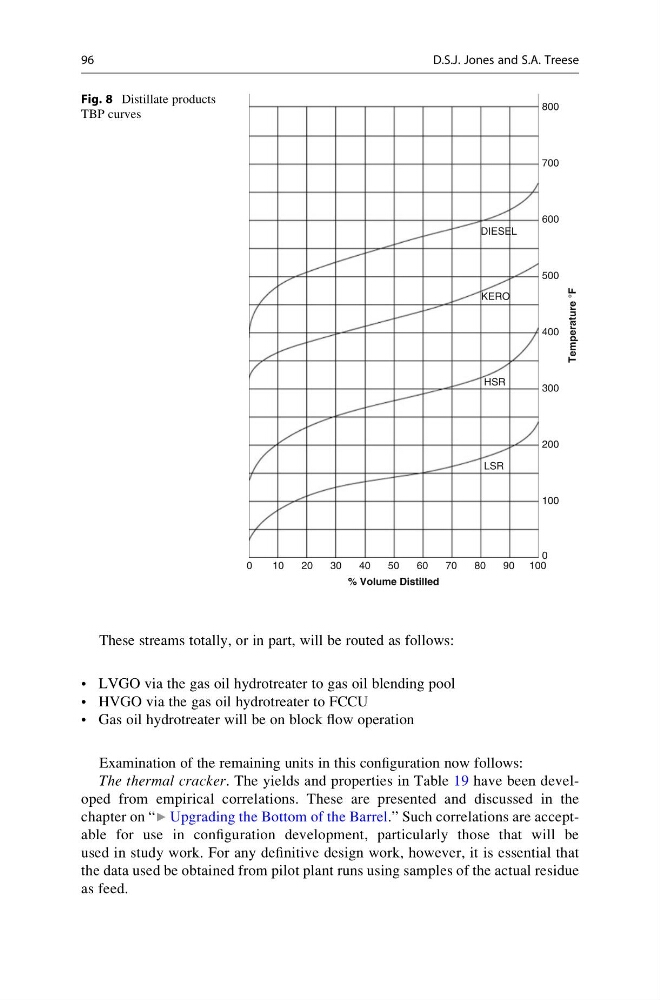
Fig. 8 Distillate products
TBP curves
96
D.S.J. Jones and S.A. Treese
• LVGO via the gas oil hydrotreater to gas oil blending pool
• HVGO via the gas oil hydrotreater to FCCU
• Gas oil hydrotreater will be on block flow operation
Examination of the remaining units in this configuration now follows:
The thermal cracker. The yields and properties in Table 19 have been developed from empirical correlations. These are presented and discussed in the
chapter on “▶ Upgrading the Bottom of the Barrel.” Such correlations are acceptable for use in configuration development, particularly those that will be
used in study work. For any definitive design work, however, it is essential that
the data used be obtained from pilot plant runs using samples of the actual residue
as feed.
800
700
600
DIESEL
KERO
HSR
LSR
500
400
Temperature °F
300
200
100
0
100
90
80
70
60
% Volume Distilled
50
40
30
20
10
0
Fig. 8 Distillate products
TBP curves
96
D.S.J. Jones and S.A. Treese