

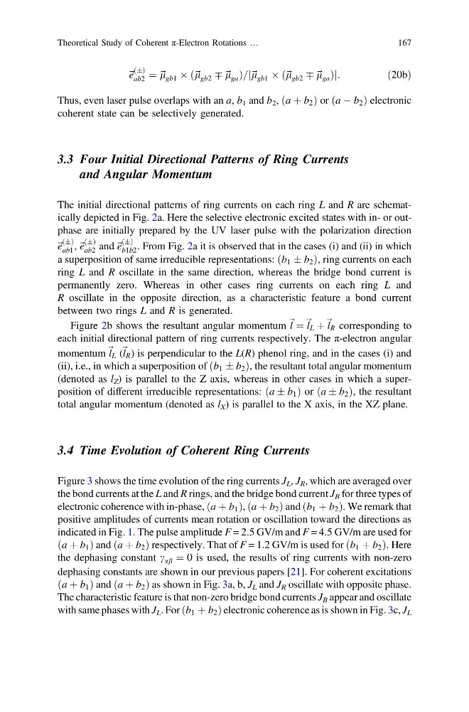
~ e
ðÆÞ
ab2 ¼ ~ l gb1 Â ð~ l gb2 Ç ~ l ga Þ=j~ l gb1 Â ð~ l gb2 Ç ~ l ga Þj:
ð20bÞ
Thus, even laser pulse overlaps with an a, b 1 and b 2 , ða þ b 2 Þ or ða À b 2 Þ electronic
coherent state can be selectively generated.
3.3 Four Initial Directional Patterns of Ring Currents
and Angular Momentum
The initial directional patterns of ring currents on each ring L and R are schematically depicted in Fig. 2a. Here the selective electronic excited states with in- or outphase are initially prepared by the UV laser pulse with the polarization direction
~ e
ðÆÞ
ab1 , ~ e
ðÆÞ
ab2 and ~ e
ðÆÞ
b1b2 . From Fig. 2a it is observed that in the cases (i) and (ii) in which
a superposition of same irreducible representations: ðb 1 Æ b 2 Þ, ring currents on each
ring L and R oscillate in the same direction, whereas the bridge bond current is
permanently zero. Whereas in other cases ring currents on each ring L and
R oscillate in the opposite direction, as a characteristic feature a bond current
between two rings L and R is generated.
Figure 2b shows the resultant angular momentum ~ l ¼ ~ l L þ ~ l R corresponding to
each initial directional pattern of ring currents respectively. The π-electron angular
momentum ~ l L ( ~ l R ) is perpendicular to the L(R) phenol ring, and in the cases (i) and
(ii), i.e., in which a superposition of ðb 1 Æ b 2 Þ, the resultant total angular momentum
(denoted as l Z ) is parallel to the Z axis, whereas in other cases in which a superposition of different irreducible representations: ða Æ b 1 Þ or ða Æ b 2 Þ, the resultant
total angular momentum (denoted as l X ) is parallel to the X axis, in the XZ plane.
3.4 Time Evolution of Coherent Ring Currents
Figure 3 shows the time evolution of the ring currents J L , J R , which are averaged over
the bond currents at the L and R rings, and the bridge bond current J B for three types of
electronic coherence with in-phase, ða þ b 1 Þ, ða þ b 2 Þ and ðb 1 þ b 2 Þ. We remark that
positive amplitudes of currents mean rotation or oscillation toward the directions as
indicated in Fig. 1. The pulse amplitude F = 2.5 GV/m and F = 4.5 GV/m are used for
ða þ b 1 Þ and ða þ b 2 Þ respectively. That of F = 1.2 GV/m is used for ðb 1 þ b 2 Þ. Here
the dephasing constant c ab ¼ 0 is used, the results of ring currents with non-zero
dephasing constants are shown in our previous papers [21]. For coherent excitations
ða þ b 1 Þ and ða þ b 2 Þ as shown in Fig. 3a, b, J L and J R oscillate with opposite phase.
The characteristic feature is that non-zero bridge bond currents J B appear and oscillate
with same phases with J L . For ðb 1 þ b 2 Þ electronic coherence as is shown in Fig. 3c, J L
Theoretical Study of Coherent π-Electron Rotations …
167
ðÆÞ
ab2 ¼ ~ l gb1 Â ð~ l gb2 Ç ~ l ga Þ=j~ l gb1 Â ð~ l gb2 Ç ~ l ga Þj:
ð20bÞ
Thus, even laser pulse overlaps with an a, b 1 and b 2 , ða þ b 2 Þ or ða À b 2 Þ electronic
coherent state can be selectively generated.
3.3 Four Initial Directional Patterns of Ring Currents
and Angular Momentum
The initial directional patterns of ring currents on each ring L and R are schematically depicted in Fig. 2a. Here the selective electronic excited states with in- or outphase are initially prepared by the UV laser pulse with the polarization direction
~ e
ðÆÞ
ab1 , ~ e
ðÆÞ
ab2 and ~ e
ðÆÞ
b1b2 . From Fig. 2a it is observed that in the cases (i) and (ii) in which
a superposition of same irreducible representations: ðb 1 Æ b 2 Þ, ring currents on each
ring L and R oscillate in the same direction, whereas the bridge bond current is
permanently zero. Whereas in other cases ring currents on each ring L and
R oscillate in the opposite direction, as a characteristic feature a bond current
between two rings L and R is generated.
Figure 2b shows the resultant angular momentum ~ l ¼ ~ l L þ ~ l R corresponding to
each initial directional pattern of ring currents respectively. The π-electron angular
momentum ~ l L ( ~ l R ) is perpendicular to the L(R) phenol ring, and in the cases (i) and
(ii), i.e., in which a superposition of ðb 1 Æ b 2 Þ, the resultant total angular momentum
(denoted as l Z ) is parallel to the Z axis, whereas in other cases in which a superposition of different irreducible representations: ða Æ b 1 Þ or ða Æ b 2 Þ, the resultant
total angular momentum (denoted as l X ) is parallel to the X axis, in the XZ plane.
3.4 Time Evolution of Coherent Ring Currents
Figure 3 shows the time evolution of the ring currents J L , J R , which are averaged over
the bond currents at the L and R rings, and the bridge bond current J B for three types of
electronic coherence with in-phase, ða þ b 1 Þ, ða þ b 2 Þ and ðb 1 þ b 2 Þ. We remark that
positive amplitudes of currents mean rotation or oscillation toward the directions as
indicated in Fig. 1. The pulse amplitude F = 2.5 GV/m and F = 4.5 GV/m are used for
ða þ b 1 Þ and ða þ b 2 Þ respectively. That of F = 1.2 GV/m is used for ðb 1 þ b 2 Þ. Here
the dephasing constant c ab ¼ 0 is used, the results of ring currents with non-zero
dephasing constants are shown in our previous papers [21]. For coherent excitations
ða þ b 1 Þ and ða þ b 2 Þ as shown in Fig. 3a, b, J L and J R oscillate with opposite phase.
The characteristic feature is that non-zero bridge bond currents J B appear and oscillate
with same phases with J L . For ðb 1 þ b 2 Þ electronic coherence as is shown in Fig. 3c, J L
Theoretical Study of Coherent π-Electron Rotations …
167