

history etc. (see Chaps. 4 and 11). Hence it is crucial to
understand how sediments may change properties during burial and uplift in order to make a good assessment of the petrophysical data that are applied in the
static and dynamic models.
22.3 Constructing the Static Reservoir
Model
Essentially, the static reservoir model is constructed in
two steps. First a structural model expressed as a 3D
modelling grid is generated, and then this grid is filled
with rock properties. An overview on this process is
outlined in Fig. 22.6. The main elements in the model
construction are:
• Model the seismic horizons and faults. Seismic
interpretation provides the most important input
for building the gross skeleton of the reservoir,
and make the seismic framework.
• As seismic resolution is limited, additional zones
may be included from well log zonation and correlation, and the conceptual model. This refinement
will outline the geological framework.
• Based on the geological framework, one or more 3D
reservoir grids are constructed. In many cases a high
resolution geological grid (also called static grid) is
made, where the actual property modelling takes
place, while a coarser flow simulation grid is
constructed for the purpose of dynamic modelling,
see Sect. 22.4.
• Property modelling is the step where each cell is
assigned various petrophysical values (such as
porosity, permeabilities and fluid saturations) and
other values (such as facies and region identifiers).
• If both a high resolution static grid and a coarser
flow simulation grid are generated, the process of
transferring properties to the coarser grid is known
as reservoir property upscaling.
In the next sections, these steps will be explained in
more detail.
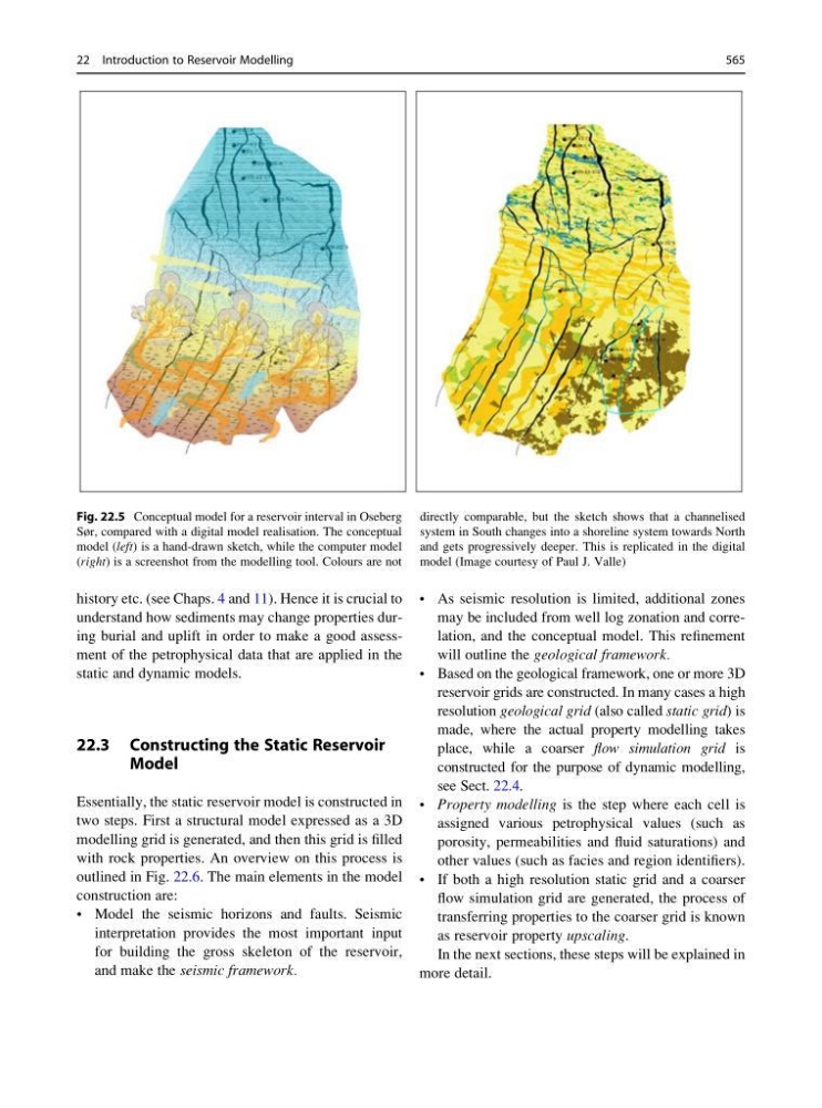
Fig. 22.5 Conceptual model for a reservoir interval in Oseberg
Sør, compared with a digital model realisation. The conceptual
model (left) is a hand-drawn sketch, while the computer model
(right) is a screenshot from the modelling tool. Colours are not
directly comparable, but the sketch shows that a channelised
system in South changes into a shoreline system towards North
and gets progressively deeper. This is replicated in the digital
model (Image courtesy of Paul J. Valle)
22 Introduction to Reservoir Modelling
565
understand how sediments may change properties during burial and uplift in order to make a good assessment of the petrophysical data that are applied in the
static and dynamic models.
22.3 Constructing the Static Reservoir
Model
Essentially, the static reservoir model is constructed in
two steps. First a structural model expressed as a 3D
modelling grid is generated, and then this grid is filled
with rock properties. An overview on this process is
outlined in Fig. 22.6. The main elements in the model
construction are:
• Model the seismic horizons and faults. Seismic
interpretation provides the most important input
for building the gross skeleton of the reservoir,
and make the seismic framework.
• As seismic resolution is limited, additional zones
may be included from well log zonation and correlation, and the conceptual model. This refinement
will outline the geological framework.
• Based on the geological framework, one or more 3D
reservoir grids are constructed. In many cases a high
resolution geological grid (also called static grid) is
made, where the actual property modelling takes
place, while a coarser flow simulation grid is
constructed for the purpose of dynamic modelling,
see Sect. 22.4.
• Property modelling is the step where each cell is
assigned various petrophysical values (such as
porosity, permeabilities and fluid saturations) and
other values (such as facies and region identifiers).
• If both a high resolution static grid and a coarser
flow simulation grid are generated, the process of
transferring properties to the coarser grid is known
as reservoir property upscaling.
In the next sections, these steps will be explained in
more detail.
Fig. 22.5 Conceptual model for a reservoir interval in Oseberg
Sør, compared with a digital model realisation. The conceptual
model (left) is a hand-drawn sketch, while the computer model
(right) is a screenshot from the modelling tool. Colours are not
directly comparable, but the sketch shows that a channelised
system in South changes into a shoreline system towards North
and gets progressively deeper. This is replicated in the digital
model (Image courtesy of Paul J. Valle)
22 Introduction to Reservoir Modelling
565