

gradients become steepened accordingly. These deep
processes influence the relief of the basin floor because
heating causes rock volumes to expand and elastic,
quasi-plastic and isostatic adjustments to occur simultaneously at lithospheric, basin (e.g. by uplift of the
basin margins) and fault block scales. In the next stage
of development (the post-rift stage), the basin will
continue to subside due to a combination of thermal
contraction, sediment compaction and sediment loading. This sounds complex, but luckily these processes
are well understood and can be modelled with good
accuracy on the basis of the algorithms proposed by
McKenzie and supplied with additional modelling
tools, developed particularly in the late 1990s.
For modelling purposes and for the analysis of
extensional basins with respect to petroleum exploration, three stages of development can be distinguished
(Fig. 12.7).
The pre-rift stage is characterised by gentle flexuring
and fracturing of the lithosphere. In some rifts we see
the development of a gentle bulge, caused by mantle
doming and associated warming – and hence expansion
– of the lithosphere. In other cases, a gentle subsidence,
defining a broad, shallow basin is seen, caused by mild
extension of the cold (not-yet-heated) lithosphere. In
both cases, the lithosphere is prone to develop steep
fractures on a crustal or even lithospheric scale. These
fractures have the capacity to accommodate magma,
generating dikes. Regarding hydrocarbon reservoir
potential characterising the pre-rift stage, sand deposits
are likely to be sheet-like and relatively thin, with few
structural traps developing at this stage. Sediment transport is mainly transverse to the basin axis, but quite
Pure shear
Simple shear
Moho
Moho
a
b
Fig. 12.5 Basic configuration of (a) pure shear and (b) simple
shear extensional basins (modified from Fossen and Gabrielsen
2005)
0
50
100
150
200
NW
Conceptual model - northern North Sea
Localised lower crustal shear zones?
SE
Moho
Moho
Moho
East Shetland Basin
Viking Graben Horda Platform Øygarden F.Z.
High velocity body
(+6 km/s)
Mantle fault
Top
Top
basement
Base Cretaceous
250
Depth (km)
Distance (km)
D2
D1
40
30
20
10
0
?
?
Distributed lower crustal deformation?
basement
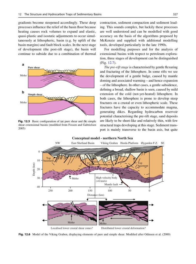
Fig. 12.6 Model of the Viking Graben, displaying elements of pure and simple shear. Modified after Odinsen et al. (2000)
12 The Structure and Hydrocarbon Traps of Sedimentary Basins
327
processes influence the relief of the basin floor because
heating causes rock volumes to expand and elastic,
quasi-plastic and isostatic adjustments to occur simultaneously at lithospheric, basin (e.g. by uplift of the
basin margins) and fault block scales. In the next stage
of development (the post-rift stage), the basin will
continue to subside due to a combination of thermal
contraction, sediment compaction and sediment loading. This sounds complex, but luckily these processes
are well understood and can be modelled with good
accuracy on the basis of the algorithms proposed by
McKenzie and supplied with additional modelling
tools, developed particularly in the late 1990s.
For modelling purposes and for the analysis of
extensional basins with respect to petroleum exploration, three stages of development can be distinguished
(Fig. 12.7).
The pre-rift stage is characterised by gentle flexuring
and fracturing of the lithosphere. In some rifts we see
the development of a gentle bulge, caused by mantle
doming and associated warming – and hence expansion
– of the lithosphere. In other cases, a gentle subsidence,
defining a broad, shallow basin is seen, caused by mild
extension of the cold (not-yet-heated) lithosphere. In
both cases, the lithosphere is prone to develop steep
fractures on a crustal or even lithospheric scale. These
fractures have the capacity to accommodate magma,
generating dikes. Regarding hydrocarbon reservoir
potential characterising the pre-rift stage, sand deposits
are likely to be sheet-like and relatively thin, with few
structural traps developing at this stage. Sediment transport is mainly transverse to the basin axis, but quite
Pure shear
Simple shear
Moho
Moho
a
b
Fig. 12.5 Basic configuration of (a) pure shear and (b) simple
shear extensional basins (modified from Fossen and Gabrielsen
2005)
0
50
100
150
200
NW
Conceptual model - northern North Sea
Localised lower crustal shear zones?
SE
Moho
Moho
Moho
East Shetland Basin
Viking Graben Horda Platform Øygarden F.Z.
High velocity body
(+6 km/s)
Mantle fault
Top
Top
basement
Base Cretaceous
250
Depth (km)
Distance (km)
D2
D1
40
30
20
10
0
?
?
Distributed lower crustal deformation?
basement
Fig. 12.6 Model of the Viking Graben, displaying elements of pure and simple shear. Modified after Odinsen et al. (2000)
12 The Structure and Hydrocarbon Traps of Sedimentary Basins
327