

280
The Stratigraphic Architecture of Fluvial Depositional Systems
NW
SE
10-2
7-1-56-15W4M
7-32
7-33
7-34
7-35 7-36·55-14W4M
B �-1.4km-�
4km---- �-1.6 km-¢--tskm-¢--,.skm-¢--t.n�-�
a•
Sf' I
R
c
Tt "Fi
1:
•'"I
"It
o;:ooY ·
I
m
II
'11 I
Datum: BASE OF FISH "�
SCALES MARKER
'
•"'\
TOP OF
MANNVILLE GROUP
TOP OF SPARKY
�L
1 km
* GAS WELL
SP Sponlonaoua Potential
R
Resisti�ity
e
Conductivity
c
c
1�
I.
��� CHANNEL SANDSTONE
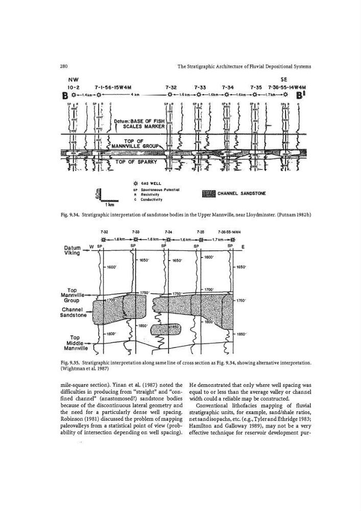
Fig. 9;34. Stratigraphic interpretation of sandstone bodies in the Upper Mannville, near Lloydminster. (Putnam 1982b)
7·32
7·33
7-34
7<35
7·36·55·14W4
*"'-1.6 km---�-1.6km---;i:E- - 1.6 kn1-"*- '·7km-*
Datum _
w sP
e
Viking
.:... ..,�------,�----H----Hc----.t-1--- -'
1600'
Top
Mann vi iile--...)+- -: :: :; ;; ;;15�
Group
Channel
Sandstone
1650'
1650'
1650'
Fig. 9.35. Stratigraphic interpretation along same line of cross section as Fig. 9.34, showing alternative interpretation.
(Wightman et a!. 1987)
mile-square section). Yinan et a!. (1987) noted the
difficulties in producing from ''straight" and ''confined channel" (anastomosed?) sandstone bodies
because of the discontinuous lateral geometry and
the need for a particularly dense well spacing.
Robinson (1981) discussed the problem of mapping
paleovalleys from a statistical point of view (probability of intersection depending on well spacing).
He demonstrated that only where well spacing was
equal to or less than the average valley or channel
width could a reliable map be constructed.
Conventional lithofacies mapping of fluvial
stratigraphic units, for example, sand/shale ratios,
net sand isopachs, etc. (e.g., Tyler and Ethridge 1983;
Hamilton and Galloway 1989), may not be a very
effective technique for reservoir development pur-
The Stratigraphic Architecture of Fluvial Depositional Systems
NW
SE
10-2
7-1-56-15W4M
7-32
7-33
7-34
7-35 7-36·55-14W4M
B �-1.4km-�
4km---- �-1.6 km-¢--tskm-¢--,.skm-¢--t.n�-�
a•
Sf' I
R
c
Tt "Fi
1:
•'"I
"It
o;:ooY ·
I
m
II
'11 I
Datum: BASE OF FISH "�
SCALES MARKER
'
•"'\
TOP OF
MANNVILLE GROUP
TOP OF SPARKY
�L
1 km
* GAS WELL
SP Sponlonaoua Potential
R
Resisti�ity
e
Conductivity
c
c
1�
I.
��� CHANNEL SANDSTONE
Fig. 9;34. Stratigraphic interpretation of sandstone bodies in the Upper Mannville, near Lloydminster. (Putnam 1982b)
7·32
7·33
7-34
7<35
7·36·55·14W4
*"'-1.6 km---�-1.6km---;i:E- - 1.6 kn1-"*- '·7km-*
Datum _
w sP
e
Viking
.:... ..,�------,�----H----Hc----.t-1--- -'
1600'
Top
Mann vi iile--...)+- -: :: :; ;; ;;15�
Group
Channel
Sandstone
1650'
1650'
1650'
Fig. 9.35. Stratigraphic interpretation along same line of cross section as Fig. 9.34, showing alternative interpretation.
(Wightman et a!. 1987)
mile-square section). Yinan et a!. (1987) noted the
difficulties in producing from ''straight" and ''confined channel" (anastomosed?) sandstone bodies
because of the discontinuous lateral geometry and
the need for a particularly dense well spacing.
Robinson (1981) discussed the problem of mapping
paleovalleys from a statistical point of view (probability of intersection depending on well spacing).
He demonstrated that only where well spacing was
equal to or less than the average valley or channel
width could a reliable map be constructed.
Conventional lithofacies mapping of fluvial
stratigraphic units, for example, sand/shale ratios,
net sand isopachs, etc. (e.g., Tyler and Ethridge 1983;
Hamilton and Galloway 1989), may not be a very
effective technique for reservoir development pur-