

254
The Stratigraphic Architecture of Fluvial Depositional Systems
a.
o __ --' 5 0km
b.
0 BLUE GRAY
SYSTEM
�
BUFF
\z._] SYSTEM
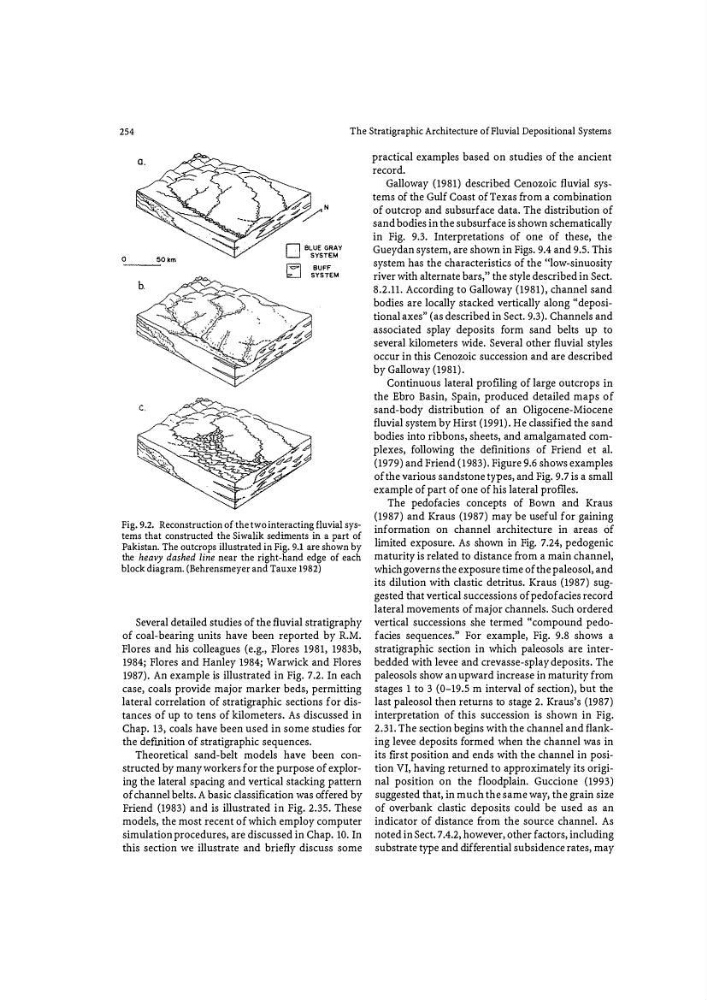
Fig. 9.2. Reconstruction of.the two interacting fluvial systems that constructed the Siwalik sediments in a part of
Pakistan. The outcrops illustrated in Fig. 9.1 are shown by
the heavy dashed line near the right-hand edge of each
block diagram. (Behrensmeyer and Tauxe 1982)
Several detailed studies of the fluvial stratigraphy
of coal-bearing units have been reported by R.M.
Flores and his colleagues (e.g., Flores 1981, 1983b,
1984; Flores and Hanley 1984; Warwick and Flores
1987). An example is illustrated in Fig. 7.2. In each
case, coals provide major marker beds, permitting
lateral correlation of stratigraphic sections for distances of up to tens of kilometers. As discussed in
Chap. 13, coals have been used in some studies for
the defmition of stratigraphic sequences.
Theoretical sand-belt models have been constructed by many workers for the purpose of exploring the lateral spacing and vertical stacking pattern
of channel belts. A basic classification was offered by
Friend (1983) and is illustrated in Fig. 2.35. These
models, the most recent of which employ computer
simulation procedures, are discussed in Chap. 10. In
this section we illustrate and briefly discuss some
practical examples based on studies of the ancient
record.
Galloway (1981) described Cenozoic fluvial systems of the Gulf Coast of Texas fr om a combination
of outcrop and subsurface data. The distribution of
sand bodies in the subsurface is shown schematically
in Fig. 9.3. Interpretations of one of these, the
Gueydan system, are shown in Figs. 9.4 and 9.5. This
system has the characteristics of the ''low-sinuosity
river with alternate bars,'' the style described in Sect.
8.2.11. According to Galloway (1981), channel sand
bodies are locally stacked vertically along "depositional axes" (as described in Sect. 9.3). Channels and
associated splay deposits fo rm sand belts up to
several kilometers wide. Several other fluvial styles
occur in this Cenozoic succession and are described
by Galloway (1981).
Continuous lateral proflling of large outcrops in
the Ebro Basin, Spain, produced detailed maps of
sand-body distribution of an Oligocene-Miocene
fluvial system by Hirst (1991). He classified the sand
bodies into ribbons, sheets, and amalgamated complexes, fo llowing the definitions of Friend et al.
(1979) and Friend (1983). Figure 9.6 shows examples
of the various sandstone types, and Fig. 9.7 is a small
example of part of one of his lateral profl.les.
The pedofacies concepts of Bown and Kraus
(1987) and Kraus (1987) may be useful for gaining
information on channel architecture in areas Of
limited exposure. As shown in Fig. 7.24, pedogenic
maturity is related to distance fr om a main channel,
which governs the exposure time of the paleosol, and
its dilution with clastic detritus. Kraus (1987) suggested that vertical successions of pedofacies record
lateral movements of major channels. Such ordered
vertical successions she termed "compound pedofacies sequences." For example, Fig. 9.8 shows a
stratigraphic section in which paleosols are interbedded with levee and crevasse-splay deposits. The
paleosols show an upward increase in maturity from
stages 1 to 3 (0-19.5 m interval of section), but the
last paleosol then returns to stage 2. Kraus's (1987)
interpretation of this succession is shown in Fig.
2.31. The section begins with the channel and flanking levee deposits formed when the channel was in
its ft rst position and ends with the channel in position VI, having returned to approximately its original position on the floodplain. Guccione (1993)
suggested that, in much the same way, the grain size
of overbank clastic deposits could be used as an
indicator of distance from the source channel. As
noted in Sect. 7.4.2, however, other factors, including
substrate type and differential subsidence rates, may
The Stratigraphic Architecture of Fluvial Depositional Systems
a.
o __ --' 5 0km
b.
0 BLUE GRAY
SYSTEM
�
BUFF
\z._] SYSTEM
Fig. 9.2. Reconstruction of.the two interacting fluvial systems that constructed the Siwalik sediments in a part of
Pakistan. The outcrops illustrated in Fig. 9.1 are shown by
the heavy dashed line near the right-hand edge of each
block diagram. (Behrensmeyer and Tauxe 1982)
Several detailed studies of the fluvial stratigraphy
of coal-bearing units have been reported by R.M.
Flores and his colleagues (e.g., Flores 1981, 1983b,
1984; Flores and Hanley 1984; Warwick and Flores
1987). An example is illustrated in Fig. 7.2. In each
case, coals provide major marker beds, permitting
lateral correlation of stratigraphic sections for distances of up to tens of kilometers. As discussed in
Chap. 13, coals have been used in some studies for
the defmition of stratigraphic sequences.
Theoretical sand-belt models have been constructed by many workers for the purpose of exploring the lateral spacing and vertical stacking pattern
of channel belts. A basic classification was offered by
Friend (1983) and is illustrated in Fig. 2.35. These
models, the most recent of which employ computer
simulation procedures, are discussed in Chap. 10. In
this section we illustrate and briefly discuss some
practical examples based on studies of the ancient
record.
Galloway (1981) described Cenozoic fluvial systems of the Gulf Coast of Texas fr om a combination
of outcrop and subsurface data. The distribution of
sand bodies in the subsurface is shown schematically
in Fig. 9.3. Interpretations of one of these, the
Gueydan system, are shown in Figs. 9.4 and 9.5. This
system has the characteristics of the ''low-sinuosity
river with alternate bars,'' the style described in Sect.
8.2.11. According to Galloway (1981), channel sand
bodies are locally stacked vertically along "depositional axes" (as described in Sect. 9.3). Channels and
associated splay deposits fo rm sand belts up to
several kilometers wide. Several other fluvial styles
occur in this Cenozoic succession and are described
by Galloway (1981).
Continuous lateral proflling of large outcrops in
the Ebro Basin, Spain, produced detailed maps of
sand-body distribution of an Oligocene-Miocene
fluvial system by Hirst (1991). He classified the sand
bodies into ribbons, sheets, and amalgamated complexes, fo llowing the definitions of Friend et al.
(1979) and Friend (1983). Figure 9.6 shows examples
of the various sandstone types, and Fig. 9.7 is a small
example of part of one of his lateral profl.les.
The pedofacies concepts of Bown and Kraus
(1987) and Kraus (1987) may be useful for gaining
information on channel architecture in areas Of
limited exposure. As shown in Fig. 7.24, pedogenic
maturity is related to distance fr om a main channel,
which governs the exposure time of the paleosol, and
its dilution with clastic detritus. Kraus (1987) suggested that vertical successions of pedofacies record
lateral movements of major channels. Such ordered
vertical successions she termed "compound pedofacies sequences." For example, Fig. 9.8 shows a
stratigraphic section in which paleosols are interbedded with levee and crevasse-splay deposits. The
paleosols show an upward increase in maturity from
stages 1 to 3 (0-19.5 m interval of section), but the
last paleosol then returns to stage 2. Kraus's (1987)
interpretation of this succession is shown in Fig.
2.31. The section begins with the channel and flanking levee deposits formed when the channel was in
its ft rst position and ends with the channel in position VI, having returned to approximately its original position on the floodplain. Guccione (1993)
suggested that, in much the same way, the grain size
of overbank clastic deposits could be used as an
indicator of distance from the source channel. As
noted in Sect. 7.4.2, however, other factors, including
substrate type and differential subsidence rates, may