

Experimental Study on Dust Removal Performance …
41
nozzles, such as spiral nozzles and powerful nozzles. There are few studies on the
classification efficiency of PM2.5 in scrubber.
In this paper, a small model experimental device with a three-liquid-inlet nozzle
was established, investigating the effects of operating parameters (e.g., liquid–gas
flow rate ratio, dust mass concentration) and the gas–liquid flow pattern on the dust
removal efficiency, providing basic data for industrial application.
Experimental
Experimental Procedure
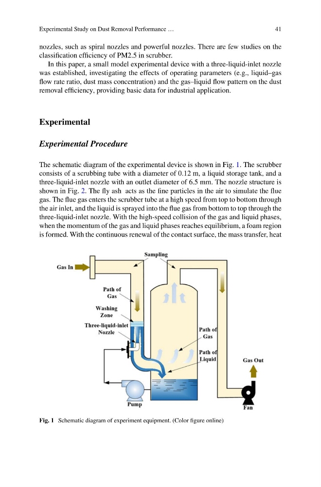
The schematic diagram of the experimental device is shown in Fig. 1. The scrubber
consists of a scrubbing tube with a diameter of 0.12 m, a liquid storage tank, and a
three-liquid-inlet nozzle with an outlet diameter of 6.5 mm. The nozzle structure is
shown in Fig. 2. The fly ash acts as the fine particles in the air to simulate the flue
gas. The flue gas enters the scrubber tube at a high speed from top to bottom through
the air inlet, and the liquid is sprayed into the flue gas from bottom to top through the
three-liquid-inlet nozzle. With the high-speed collision of the gas and liquid phases,
when the momentum of the gas and liquid phases reaches equilibrium, a foam region
is formed. With the continuous renewal of the contact surface, the mass transfer, heat
Fig. 1 Schematic diagram of experiment equipment. (Color figure online)
41
nozzles, such as spiral nozzles and powerful nozzles. There are few studies on the
classification efficiency of PM2.5 in scrubber.
In this paper, a small model experimental device with a three-liquid-inlet nozzle
was established, investigating the effects of operating parameters (e.g., liquid–gas
flow rate ratio, dust mass concentration) and the gas–liquid flow pattern on the dust
removal efficiency, providing basic data for industrial application.
Experimental
Experimental Procedure
The schematic diagram of the experimental device is shown in Fig. 1. The scrubber
consists of a scrubbing tube with a diameter of 0.12 m, a liquid storage tank, and a
three-liquid-inlet nozzle with an outlet diameter of 6.5 mm. The nozzle structure is
shown in Fig. 2. The fly ash acts as the fine particles in the air to simulate the flue
gas. The flue gas enters the scrubber tube at a high speed from top to bottom through
the air inlet, and the liquid is sprayed into the flue gas from bottom to top through the
three-liquid-inlet nozzle. With the high-speed collision of the gas and liquid phases,
when the momentum of the gas and liquid phases reaches equilibrium, a foam region
is formed. With the continuous renewal of the contact surface, the mass transfer, heat
Fig. 1 Schematic diagram of experiment equipment. (Color figure online)