

mλ ¼ d sin α þ sin β
ð
Þ
ð 4:19Þ
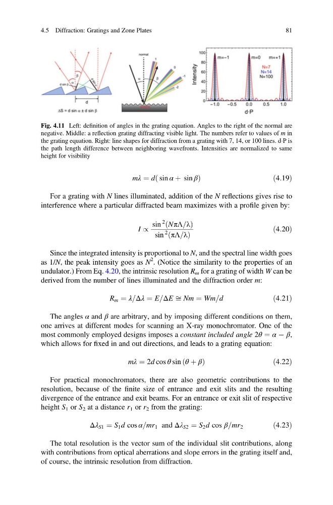
For a grating with N lines illuminated, addition of the N reflections gives rise to
interference where a particular diffracted beam maximizes with a profile given by:
I /
sin
2 NπΛ=λ
ð
Þ
sin
2
πΛ=λ
ð
Þ
ð4:20Þ
Since the integrated intensity is proportional to N, and the spectral line width goes
as 1/N, the peak intensity goes as N
2 . (Notice the similarity to the properties of an
undulator.) From Eq. 4.20, the intrinsic resolution R m for a grating of width W can be
derived from the number of lines illuminated and the diffraction order m:
R m ¼ λ=Δλ ¼ E=ΔE ffi Nm ¼ Wm=d
ð4:21Þ
The angles α and β are arbitrary, and by imposing different conditions on them,
one arrives at different modes for scanning an X-ray monochromator. One of the
most commonly employed designs imposes a constant included angle 2θ ¼ α À β,
which allows for fixed in and out directions, and leads to a grating equation:
mλ ¼ 2d cos θ sin θ þ β
ð
Þ
ð4:22Þ
For practical monochromators, there are also geometric contributions to the
resolution, because of the finite size of entrance and exit slits and the resulting
divergence of the entrance and exit beams. For an entrance or exit slit of respective
height S 1 or S 2 at a distance r 1 or r 2 from the grating:
Δλ S1 ¼ S 1 d cos α=mr 1 and Δλ S2 ¼ S 2 d cos β=mr 2
ð4:23Þ
The total resolution is the vector sum of the individual slit contributions, along
with contributions from optical aberrations and slope errors in the grating itself and,
of course, the intrinsic resolution from diffraction.
Fig. 4.11 Left: definition of angles in the grating equation. Angles to the right of the normal are
negative. Middle: a reflection grating diffracting visible light. The numbers refer to values of m in
the grating equation. Right: line shapes for diffraction from a grating with 7, 14, or 100 lines. dÁP is
the path length difference between neighboring wavefronts. Intensities are normalized to same
height for visibility
4.5 Diffraction: Gratings and Zone Plates
81
ð
Þ
ð 4:19Þ
For a grating with N lines illuminated, addition of the N reflections gives rise to
interference where a particular diffracted beam maximizes with a profile given by:
I /
sin
2 NπΛ=λ
ð
Þ
sin
2
πΛ=λ
ð
Þ
ð4:20Þ
Since the integrated intensity is proportional to N, and the spectral line width goes
as 1/N, the peak intensity goes as N
2 . (Notice the similarity to the properties of an
undulator.) From Eq. 4.20, the intrinsic resolution R m for a grating of width W can be
derived from the number of lines illuminated and the diffraction order m:
R m ¼ λ=Δλ ¼ E=ΔE ffi Nm ¼ Wm=d
ð4:21Þ
The angles α and β are arbitrary, and by imposing different conditions on them,
one arrives at different modes for scanning an X-ray monochromator. One of the
most commonly employed designs imposes a constant included angle 2θ ¼ α À β,
which allows for fixed in and out directions, and leads to a grating equation:
mλ ¼ 2d cos θ sin θ þ β
ð
Þ
ð4:22Þ
For practical monochromators, there are also geometric contributions to the
resolution, because of the finite size of entrance and exit slits and the resulting
divergence of the entrance and exit beams. For an entrance or exit slit of respective
height S 1 or S 2 at a distance r 1 or r 2 from the grating:
Δλ S1 ¼ S 1 d cos α=mr 1 and Δλ S2 ¼ S 2 d cos β=mr 2
ð4:23Þ
The total resolution is the vector sum of the individual slit contributions, along
with contributions from optical aberrations and slope errors in the grating itself and,
of course, the intrinsic resolution from diffraction.
Fig. 4.11 Left: definition of angles in the grating equation. Angles to the right of the normal are
negative. Middle: a reflection grating diffracting visible light. The numbers refer to values of m in
the grating equation. Right: line shapes for diffraction from a grating with 7, 14, or 100 lines. dÁP is
the path length difference between neighboring wavefronts. Intensities are normalized to same
height for visibility
4.5 Diffraction: Gratings and Zone Plates
81