

3.8.2 Elliptical Undulator Fundamental Wavelength
and Energy
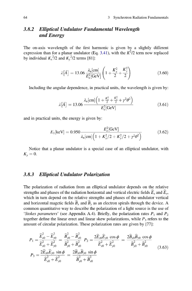
The on-axis wavelength of the first harmonic is given by a slightly different
expression than for a planar undulator (Eq. 3.41), with the K
2 /2 term now replaced
by individual K x
2
/2 and K y
2 /2 terms [81]:
λ Å
 à ¼ 13:06
λ u cm
½
E
2
e GeV
½
1 þ
K
2
x
2
þ
K
2
y
2
!
ð3:60Þ
Including the angular dependence, in practical units, the wavelength is given by:
λ Å
 à ¼ 13:06
λ u cm
½ 1 þ
K
2
x
2 þ
K
2
y
2 þ γ
2
θ
2
E
2
e GeV
½
ð3:61Þ
and in practical units, the energy is given by:
E 1 keV
½
¼ 0:950
E
2
e GeV
½
λ u cm
½ 1 þ K
2
x =2 þ K
2
y =2 þ γ 2 θ
2
ð3:62Þ
Notice that a planar undulator is a special case of an elliptical undulator, with
K y ¼ 0.
3.8.3 Elliptical Undulator Polarization
The polarization of radiation from an elliptical undulator depends on the relative
strengths and phases of the radiation horizontal and vertical electric fields b
E x and b
E y ,
which in turn depend on the relative strengths and phases of the undulator vertical
and horizontal magetic fields b
B x and b
B y as an electron spirals through the device. A
common quantitative way to describe the polarization of a light source is the use of
‘Stokes parameters’ (see Appendix A.4). Briefly, the polarization rates P 1 and P 2
together define the linear erect and linear skew polarizations, while P 3 refers to the
amount of circular polarization. These polarization rates are given by [77]:
P 1 ¼
b
E
2
x0 À b
E
2
y0
b
E
2
x0 þ b
E
2
y0
¼
b
B
2
y0 À b
B
2
x0
b
B
2
y0 þ b
B
2
x0
P 2 ¼
2 b
E x0 b
E y0 cos ϕ
b
E
2
x0 þ b
E
2
y0
¼
2 b
B x0 b
B y0 cos ϕ
b
B
2
y0 þ b
B
2
x0
P 3 ¼
2 b
E x0 b
E y0 sin ϕ
b
E
2
x0 þ b
E
2
y0
¼
2 b
B x0 b
B y0 sin ϕ
b
B
2
y0 þ b
B
2
x0
ð3:63Þ
64
3 Synchrotron Radiation Fundamentals
and Energy
The on-axis wavelength of the first harmonic is given by a slightly different
expression than for a planar undulator (Eq. 3.41), with the K
2 /2 term now replaced
by individual K x
2
/2 and K y
2 /2 terms [81]:
λ Å
 à ¼ 13:06
λ u cm
½
E
2
e GeV
½
1 þ
K
2
x
2
þ
K
2
y
2
!
ð3:60Þ
Including the angular dependence, in practical units, the wavelength is given by:
λ Å
 à ¼ 13:06
λ u cm
½ 1 þ
K
2
x
2 þ
K
2
y
2 þ γ
2
θ
2
E
2
e GeV
½
ð3:61Þ
and in practical units, the energy is given by:
E 1 keV
½
¼ 0:950
E
2
e GeV
½
λ u cm
½ 1 þ K
2
x =2 þ K
2
y =2 þ γ 2 θ
2
ð3:62Þ
Notice that a planar undulator is a special case of an elliptical undulator, with
K y ¼ 0.
3.8.3 Elliptical Undulator Polarization
The polarization of radiation from an elliptical undulator depends on the relative
strengths and phases of the radiation horizontal and vertical electric fields b
E x and b
E y ,
which in turn depend on the relative strengths and phases of the undulator vertical
and horizontal magetic fields b
B x and b
B y as an electron spirals through the device. A
common quantitative way to describe the polarization of a light source is the use of
‘Stokes parameters’ (see Appendix A.4). Briefly, the polarization rates P 1 and P 2
together define the linear erect and linear skew polarizations, while P 3 refers to the
amount of circular polarization. These polarization rates are given by [77]:
P 1 ¼
b
E
2
x0 À b
E
2
y0
b
E
2
x0 þ b
E
2
y0
¼
b
B
2
y0 À b
B
2
x0
b
B
2
y0 þ b
B
2
x0
P 2 ¼
2 b
E x0 b
E y0 cos ϕ
b
E
2
x0 þ b
E
2
y0
¼
2 b
B x0 b
B y0 cos ϕ
b
B
2
y0 þ b
B
2
x0
P 3 ¼
2 b
E x0 b
E y0 sin ϕ
b
E
2
x0 þ b
E
2
y0
¼
2 b
B x0 b
B y0 sin ϕ
b
B
2
y0 þ b
B
2
x0
ð3:63Þ
64
3 Synchrotron Radiation Fundamentals