

articles and books cited at the end of this chapter. After planar undulators, the
elliptical undulator is treated as a flexible device that can produce variable linear
or circular polarization. Finally, we briefly mention the helical undulator as a special
case for circular polarization.
In an undulator, the output exhibits interference effects between the radiation
from different pole regions. This is because the natural opening angle of synchrotron
radiation is greater than the angular deflection of the electron trajectory, and an
observer cannot distinguish which pole is the source of the radiation. As with a
diffraction grating, in order to calculate the final intensity, one has to add the fields
from different sources to compute the total field and then square to get the intensity.
The basic spectrum of a planar undulator is actually easier to understand than that
of a bend magnet. Suppose one is traveling in a reference frame along with the
relativistic electron as it encounters the undulator structure. In the limit of very small
electron horizontal excursions, the observer sees an electron oscillating back and
forth with the spatial period of the undulator, λ u , but shortened by the relativistic
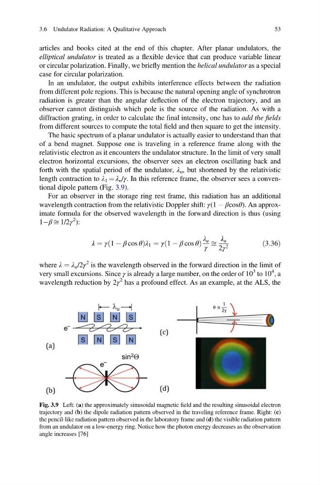
length contraction to λ 1 ¼ λ u /γ. In this reference frame, the observer sees a conventional dipole pattern (Fig. 3.9).
For an observer in the storage ring rest frame, this radiation has an additional
wavelength contraction from the relativistic Doppler shift: γ(1 À βcosθ). An approximate formula for the observed wavelength in the forward direction is thus (using
1Àβ ffi 1/2γ
2 ):
λ ¼ γ 1 À β cos θ
ð
Þ λ 1 ¼ γ 1 À β cos θ
ð
Þ
λ u
γ
ffi
λ u
2γ 2
ð3:36Þ
where λ ¼ λ u /2γ
2 is the wavelength observed in the forward direction in the limit of
very small excursions. Since γ is already a large number, on the order of 10
3 to 10
4 , a
wavelength reduction by 2γ
2 has a profound effect. As an example, at the ALS, the
Fig. 3.9 Left: (a) the approximately sinusoidal magnetic field and the resulting sinusoidal electron
trajectory and (b) the dipole radiation pattern observed in the traveling reference frame. Right: (c)
the pencil-like radiation pattern observed in the laboratory frame and (d) the visible radiation pattern
from an undulator on a low-energy ring. Notice how the photon energy decreases as the observation
angle increases [76]
3.6 Undulator Radiation: A Qualitative Approach
53
elliptical undulator is treated as a flexible device that can produce variable linear
or circular polarization. Finally, we briefly mention the helical undulator as a special
case for circular polarization.
In an undulator, the output exhibits interference effects between the radiation
from different pole regions. This is because the natural opening angle of synchrotron
radiation is greater than the angular deflection of the electron trajectory, and an
observer cannot distinguish which pole is the source of the radiation. As with a
diffraction grating, in order to calculate the final intensity, one has to add the fields
from different sources to compute the total field and then square to get the intensity.
The basic spectrum of a planar undulator is actually easier to understand than that
of a bend magnet. Suppose one is traveling in a reference frame along with the
relativistic electron as it encounters the undulator structure. In the limit of very small
electron horizontal excursions, the observer sees an electron oscillating back and
forth with the spatial period of the undulator, λ u , but shortened by the relativistic
length contraction to λ 1 ¼ λ u /γ. In this reference frame, the observer sees a conventional dipole pattern (Fig. 3.9).
For an observer in the storage ring rest frame, this radiation has an additional
wavelength contraction from the relativistic Doppler shift: γ(1 À βcosθ). An approximate formula for the observed wavelength in the forward direction is thus (using
1Àβ ffi 1/2γ
2 ):
λ ¼ γ 1 À β cos θ
ð
Þ λ 1 ¼ γ 1 À β cos θ
ð
Þ
λ u
γ
ffi
λ u
2γ 2
ð3:36Þ
where λ ¼ λ u /2γ
2 is the wavelength observed in the forward direction in the limit of
very small excursions. Since γ is already a large number, on the order of 10
3 to 10
4 , a
wavelength reduction by 2γ
2 has a profound effect. As an example, at the ALS, the
Fig. 3.9 Left: (a) the approximately sinusoidal magnetic field and the resulting sinusoidal electron
trajectory and (b) the dipole radiation pattern observed in the traveling reference frame. Right: (c)
the pencil-like radiation pattern observed in the laboratory frame and (d) the visible radiation pattern
from an undulator on a low-energy ring. Notice how the photon energy decreases as the observation
angle increases [76]
3.6 Undulator Radiation: A Qualitative Approach
53