

2.4 Other Components
2.4.1 Booster Synchrotrons
A linear accelerator with the same final particle energy as the storage ring is usually
unjustifiably large and expensive. A common and cheaper approach is to use a
booster synchrotron as an intermediate step in raising the particle energy. A synchrotron is simply a rapidly tunable storage ring. Electrons are injected into the
synchrotron at relatively low energies, and as the particles acquire energy from the rf
cavity, the fields in the bend magnets are ramped to maintain a constant bend radius.
For example, at the ALS, the booster synchrotron dipoles are ramped from near zero
to 1.2 Tesla in about 0.5 s. The magnets are then ramped down, the synchrotron
refilled, and the process starts over again.
2.4.2 The Brief Flirtation with Positrons
If you read the early literature about third-generation high-energy sources, you will
come across references to positron storage that might be confusing. The stored
particle beam tends to make positive ions from collisions with residual gas molecules
in the vacuum chamber. In theory, these ions form a cloud that is attracted to the
negative charge of an electron beam, and collisions with these ions reduce the stored
beam lifetime [27]. To avoid this “ion trapping,” many thought it better to store
positive particles than negative particles. So, in another layer of complexity, some of
the brightest high-energy rings (APS and PETRA-III) planned to store positrons
instead of electrons.
In these schemes, positrons are created by directing high-energy electrons onto a
tungsten target, yielding positrons via bremsstrahlung pair production. The collected
positrons are accelerated in their own short linac and stored in a small “positron
accumulator ring” (“PAR”) before injection into the booster synchrotron. Although
positron storage had a certain elegance, over time, other solutions were found to the
ion trapping problem. Both APS and PETRA-III switched back to electrons.
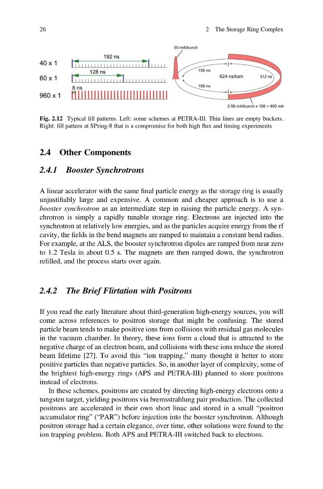
Fig. 2.12 Typical fill patterns. Left: some schemes at PETRA-III. Thin lines are empty buckets.
Right: fill pattern at SPring-8 that is a compromise for both high flux and timing experiments
26
2 The Storage Ring Complex
2.4.1 Booster Synchrotrons
A linear accelerator with the same final particle energy as the storage ring is usually
unjustifiably large and expensive. A common and cheaper approach is to use a
booster synchrotron as an intermediate step in raising the particle energy. A synchrotron is simply a rapidly tunable storage ring. Electrons are injected into the
synchrotron at relatively low energies, and as the particles acquire energy from the rf
cavity, the fields in the bend magnets are ramped to maintain a constant bend radius.
For example, at the ALS, the booster synchrotron dipoles are ramped from near zero
to 1.2 Tesla in about 0.5 s. The magnets are then ramped down, the synchrotron
refilled, and the process starts over again.
2.4.2 The Brief Flirtation with Positrons
If you read the early literature about third-generation high-energy sources, you will
come across references to positron storage that might be confusing. The stored
particle beam tends to make positive ions from collisions with residual gas molecules
in the vacuum chamber. In theory, these ions form a cloud that is attracted to the
negative charge of an electron beam, and collisions with these ions reduce the stored
beam lifetime [27]. To avoid this “ion trapping,” many thought it better to store
positive particles than negative particles. So, in another layer of complexity, some of
the brightest high-energy rings (APS and PETRA-III) planned to store positrons
instead of electrons.
In these schemes, positrons are created by directing high-energy electrons onto a
tungsten target, yielding positrons via bremsstrahlung pair production. The collected
positrons are accelerated in their own short linac and stored in a small “positron
accumulator ring” (“PAR”) before injection into the booster synchrotron. Although
positron storage had a certain elegance, over time, other solutions were found to the
ion trapping problem. Both APS and PETRA-III switched back to electrons.
Fig. 2.12 Typical fill patterns. Left: some schemes at PETRA-III. Thin lines are empty buckets.
Right: fill pattern at SPring-8 that is a compromise for both high flux and timing experiments
26
2 The Storage Ring Complex