

7.6.5 Charge Transfer
For highly ionic systems, such as Mn
2+ , a single electron configuration such as 3d
5
suffices to describe the initial state. However, for more covalent systems, one has to
recognize the possibility of covalent charge-sharing between the metal and the
ligand system. In the charge-transfer multiplet model, this is done by including
one or more extra configurations, described as:
3d
n
þ L3d
nþ1
ð7:9Þ
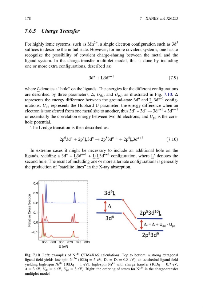
where L denotes a “hole” on the ligands. The energies for the different configurations
are described by three parameters, Δ, U dd , and U pd , as illustrated in Fig. 7.10. Δ
represents the energy difference between the ground-state 3d
n and L 3d
n+1 configurations; U dd represents the Hubbard U parameter, the energy difference when an
electron is transferred from one metal site to another, thus 3d
n + 3d
n ! 3d
n+1 + 3d
nÀ1
or essentially the correlation energy between two 3d electrons; and U pd is the corehole potential.
The L-edge transition is then described as:
2p
6 3d
n
þ 2p
6 L3d
n
! 2p
5 3d
nþ1
þ 2p
5 L3d
nþ2
ð7:10Þ
In extreme cases it might be necessary to include an additional hole on the
ligands, yielding a 3d
n + L3d
n+1 + L
0 L3d
n+2 configuration, where L
0 denotes the
second hole. The result of including one or more alternate configurations is generally
the production of “satellite lines” in the X-ray absorption.
0.4
0.3
0.2
0.1
0.0
–0.1
855 860
870 875 880
865
E (eV)
Relative Cross Section
Fig. 7.10 Left: examples of Ni
2+ CTM4XAS calculations. Top to bottom: a strong tetragonal
ligand field yields low-spin Ni
2+ (10Dq ¼ 5 eV, Ds ¼ Dt ¼ 0.8 eV); an octahedral ligand field
yielding high-spin Ni
2+ (10Dq ¼ 1 eV); high-spin Ni
2+ with charge transfer (10Dq ¼ 0.7 eV,
Δ ¼ 3 eV, U dd ¼ 6 eV, U pd ¼ 8 eV). Right: the ordering of states for Ni
2+ in the charge-transfer
multiplet model
178
7 XANES and XMCD
For highly ionic systems, such as Mn
2+ , a single electron configuration such as 3d
5
suffices to describe the initial state. However, for more covalent systems, one has to
recognize the possibility of covalent charge-sharing between the metal and the
ligand system. In the charge-transfer multiplet model, this is done by including
one or more extra configurations, described as:
3d
n
þ L3d
nþ1
ð7:9Þ
where L denotes a “hole” on the ligands. The energies for the different configurations
are described by three parameters, Δ, U dd , and U pd , as illustrated in Fig. 7.10. Δ
represents the energy difference between the ground-state 3d
n and L 3d
n+1 configurations; U dd represents the Hubbard U parameter, the energy difference when an
electron is transferred from one metal site to another, thus 3d
n + 3d
n ! 3d
n+1 + 3d
nÀ1
or essentially the correlation energy between two 3d electrons; and U pd is the corehole potential.
The L-edge transition is then described as:
2p
6 3d
n
þ 2p
6 L3d
n
! 2p
5 3d
nþ1
þ 2p
5 L3d
nþ2
ð7:10Þ
In extreme cases it might be necessary to include an additional hole on the
ligands, yielding a 3d
n + L3d
n+1 + L
0 L3d
n+2 configuration, where L
0 denotes the
second hole. The result of including one or more alternate configurations is generally
the production of “satellite lines” in the X-ray absorption.
0.4
0.3
0.2
0.1
0.0
–0.1
855 860
870 875 880
865
E (eV)
Relative Cross Section
Fig. 7.10 Left: examples of Ni
2+ CTM4XAS calculations. Top to bottom: a strong tetragonal
ligand field yields low-spin Ni
2+ (10Dq ¼ 5 eV, Ds ¼ Dt ¼ 0.8 eV); an octahedral ligand field
yielding high-spin Ni
2+ (10Dq ¼ 1 eV); high-spin Ni
2+ with charge transfer (10Dq ¼ 0.7 eV,
Δ ¼ 3 eV, U dd ¼ 6 eV, U pd ¼ 8 eV). Right: the ordering of states for Ni
2+ in the charge-transfer
multiplet model
178
7 XANES and XMCD