

4.6.4 Crystal Polarizers
Crystals can also be used as quarter-wave plates to produce circularly polarized
X-rays. As a reminder, a linearly polarized beam traveling in the z-direction can
always be reconsidered as the sum of two perpendicular components, say:
E
!
z, t
ð Þ ¼ b i E σ cos ω t À n σ z=c
ð
Þ
½
þ b jE π cos ω t À n π z=c
ð
Þ
½
ð 4:37Þ
where b i and b j are unit vectors in orthogonal directions, E σ and E π are the amplitudes
in those directions, and n σ and n π are the refractive indices in those directions. For
linear polarization, the relative amplitudes of E σ and E π determine the polarization
orientation, and for ordinary materials, n σ and n π are equal. But, in some cases,
materials can have different indices of refraction for different electric field directions—they are “birefringent.” This “birefringence” causes a phase difference Δφ to
accumulate between the two components as the beam propagates through distance l:
Δφ ¼
2π
λ 0
l n σ À n π
ð
Þ
ð 4:38Þ
If an optic introduces different phase shifts for these two directions, then it will
change the polarization of the transmitted beam. (With visible light, the most
familiar example is Iceland spar.) In particular, if the difference in phase shifts is
π/2, then the optic is called a “quarter-wave plate,” and the transmitted beam will
have circular polarization.
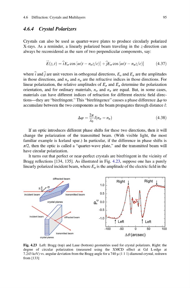
It turns out that perfect or near-perfect crystals are birefringent in the vicinity of
Bragg reflections [134, 135]. As illustrated in Fig. 4.23, suppose one has a purely
linearly polarized incident beam, where E π is the amplitude of the electric field in the
Fig. 4.23 Left: Bragg (top) and Laue (bottom) geometries used for crystal polarizers. Right: the
degree of circular polarization (measured using the XMCD effect at Gd L-edge at
7.243 keV) vs. angular deviation from the Bragg angle for a 740 μ (1 1 1) diamond crystal, redrawn
from [133]
4.6 Diffraction: Crystals and Multilayers
95
Crystals can also be used as quarter-wave plates to produce circularly polarized
X-rays. As a reminder, a linearly polarized beam traveling in the z-direction can
always be reconsidered as the sum of two perpendicular components, say:
E
!
z, t
ð Þ ¼ b i E σ cos ω t À n σ z=c
ð
Þ
½
þ b jE π cos ω t À n π z=c
ð
Þ
½
ð 4:37Þ
where b i and b j are unit vectors in orthogonal directions, E σ and E π are the amplitudes
in those directions, and n σ and n π are the refractive indices in those directions. For
linear polarization, the relative amplitudes of E σ and E π determine the polarization
orientation, and for ordinary materials, n σ and n π are equal. But, in some cases,
materials can have different indices of refraction for different electric field directions—they are “birefringent.” This “birefringence” causes a phase difference Δφ to
accumulate between the two components as the beam propagates through distance l:
Δφ ¼
2π
λ 0
l n σ À n π
ð
Þ
ð 4:38Þ
If an optic introduces different phase shifts for these two directions, then it will
change the polarization of the transmitted beam. (With visible light, the most
familiar example is Iceland spar.) In particular, if the difference in phase shifts is
π/2, then the optic is called a “quarter-wave plate,” and the transmitted beam will
have circular polarization.
It turns out that perfect or near-perfect crystals are birefringent in the vicinity of
Bragg reflections [134, 135]. As illustrated in Fig. 4.23, suppose one has a purely
linearly polarized incident beam, where E π is the amplitude of the electric field in the
Fig. 4.23 Left: Bragg (top) and Laue (bottom) geometries used for crystal polarizers. Right: the
degree of circular polarization (measured using the XMCD effect at Gd L-edge at
7.243 keV) vs. angular deviation from the Bragg angle for a 740 μ (1 1 1) diamond crystal, redrawn
from [133]
4.6 Diffraction: Crystals and Multilayers
95