

devoid of any H-bonds forms. In this structure, the dimer cannot dissociate
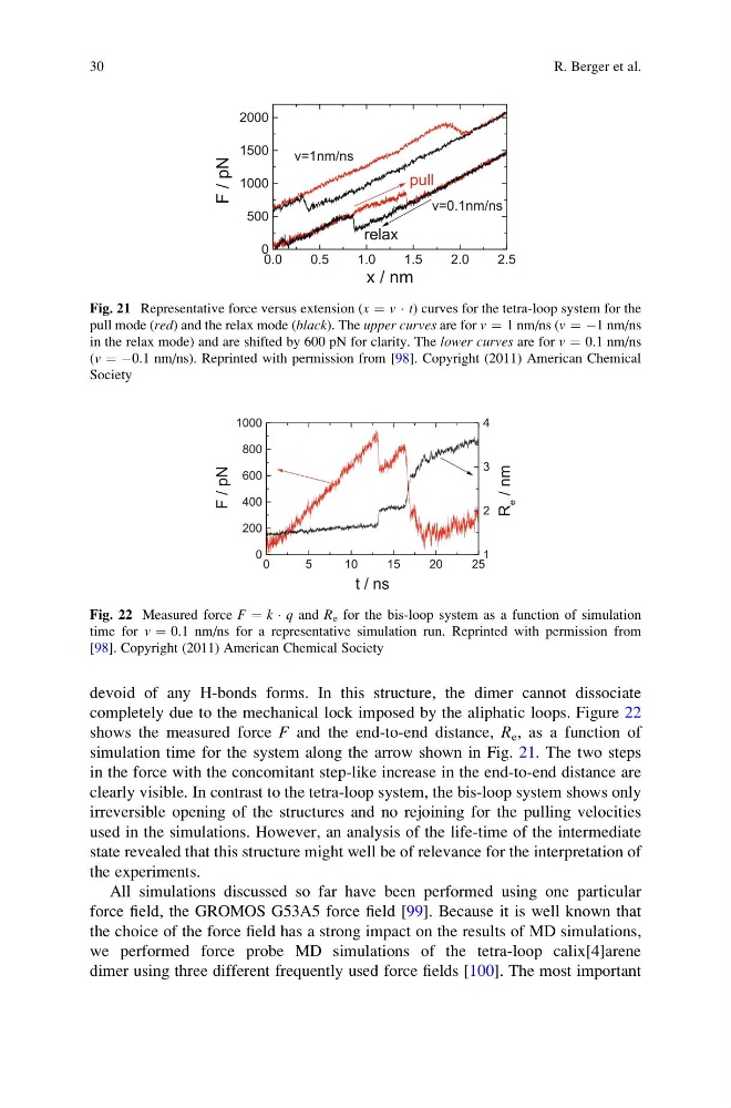
completely due to the mechanical lock imposed by the aliphatic loops. Figure 22
shows the measured force F and the end-to-end distance, R e , as a function of
simulation time for the system along the arrow shown in Fig. 21. The two steps
in the force with the concomitant step-like increase in the end-to-end distance are
clearly visible. In contrast to the tetra-loop system, the bis-loop system shows only
irreversible opening of the structures and no rejoining for the pulling velocities
used in the simulations. However, an analysis of the life-time of the intermediate
state revealed that this structure might well be of relevance for the interpretation of
the experiments.
All simulations discussed so far have been performed using one particular
force field, the GROMOS G53A5 force field [99]. Because it is well known that
the choice of the force field has a strong impact on the results of MD simulations,
we performed force probe MD simulations of the tetra-loop calix[4]arene
dimer using three different frequently used force fields [100]. The most important
Fig. 21 Representative force versus extension (x ¼ v Á t) curves for the tetra-loop system for the
pull mode (red) and the relax mode (black). The upper curves are for v ¼ 1 nm/ns (v ¼ À1 nm/ns
in the relax mode) and are shifted by 600 pN for clarity. The lower curves are for v ¼ 0.1 nm/ns
(v ¼ À0.1 nm/ns). Reprinted with permission from [98]. Copyright (2011) American Chemical
Society
Fig. 22 Measured force F ¼ k Á q and R e for the bis-loop system as a function of simulation
time for v ¼ 0.1 nm/ns for a representative simulation run. Reprinted with permission from
[98]. Copyright (2011) American Chemical Society
30
R. Berger et al.
completely due to the mechanical lock imposed by the aliphatic loops. Figure 22
shows the measured force F and the end-to-end distance, R e , as a function of
simulation time for the system along the arrow shown in Fig. 21. The two steps
in the force with the concomitant step-like increase in the end-to-end distance are
clearly visible. In contrast to the tetra-loop system, the bis-loop system shows only
irreversible opening of the structures and no rejoining for the pulling velocities
used in the simulations. However, an analysis of the life-time of the intermediate
state revealed that this structure might well be of relevance for the interpretation of
the experiments.
All simulations discussed so far have been performed using one particular
force field, the GROMOS G53A5 force field [99]. Because it is well known that
the choice of the force field has a strong impact on the results of MD simulations,
we performed force probe MD simulations of the tetra-loop calix[4]arene
dimer using three different frequently used force fields [100]. The most important
Fig. 21 Representative force versus extension (x ¼ v Á t) curves for the tetra-loop system for the
pull mode (red) and the relax mode (black). The upper curves are for v ¼ 1 nm/ns (v ¼ À1 nm/ns
in the relax mode) and are shifted by 600 pN for clarity. The lower curves are for v ¼ 0.1 nm/ns
(v ¼ À0.1 nm/ns). Reprinted with permission from [98]. Copyright (2011) American Chemical
Society
Fig. 22 Measured force F ¼ k Á q and R e for the bis-loop system as a function of simulation
time for v ¼ 0.1 nm/ns for a representative simulation run. Reprinted with permission from
[98]. Copyright (2011) American Chemical Society
30
R. Berger et al.