

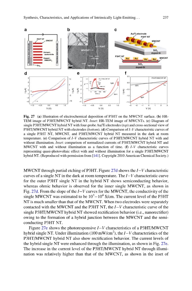
MWCNT through partial etching of P3HT. Figure 27d shows the IÀV characteristic
curves of a single NT in the dark at room temperature. The IÀV characteristic curve
for the outer P3HT single NT in the hybrid NT shows semiconducting behavior,
whereas ohmic behavior is observed for the inner single MWCNT, as shown in
Fig. 27d. From the slope of the IÀV curves for the MWCNT, the conductivity of the
single MWCNT was estimated to be 10
3
À10
4 S/cm. The current level of the P3HT
NT is much smaller than that of the MWCNT. When two electrodes were separately
contacted with the MWCNT and the P3HT NT, the IÀV characteristic curve of the
single P3HT/MWCNT hybrid NT showed rectification behavior (i.e., nanorectifier)
owing to the formation of a hybrid junction between the MWCNT and the semiconducting P3HT NT.
Figure 27e shows the photoresponsive IÀV characteristics of a P3HT/MWCNT
hybrid single NT. Under illumination (100 mW/cm
2 ), the IÀV characteristics of the
P3HT/MWCNT hybrid NT also show rectification behavior. The current levels of
the hybrid single NT were enhanced through the illumination, as shown in Fig. 27e.
The increase in the current level of the P3HT/MWCNT hybrid NT through illumination was relatively higher than that of the MWCNT, as shown in the inset of
V (V)
V (V)
V (V)
I (nA)
I (μA)
I (μA)
I (μA)
–3
–2
–1
0
1
2
3
1.0
1.0
0
3
P3HT/MWCNT NT
time (s)
600
400
200
0
M0
2.0
1.5
1.0
MWCNT
light
on
light
off
P3HT/MWCNT NT
dark
dark
light
light
Isc
Voc
2
1
–1
–2
–3
0.5
0.5
0.0
0.0
3
–1
0
0.5
P3HT NT
Au/Ti electrode
P3HT NT
MWCNT
MWCNT
doped-Si
doped-Si
SiO2
SiO2
Au
Au
Au
Au
c
d
a
f
e
b
0.0
– 0.5
–1.0
–1.5
–5
–10
10
Doped-Si
Sio2
Dopant :
BMIMPF6
Solvent :
acetonitrile
MWCNT
Stainless steel electrode
Stainless steel electrode
P3HT NT
5
0
1
2
4
5
– 60 nm
MWCNT
P3HT
–15 nm
20 nm
– 0.5
– 0.5
–1.0
–1.0
Fig. 27 (a) Illustration of electrochemical deposition of P3HT on the MWCNT surface. (b) HRTEM image of P3HT/MWCNT hybrid NT. Inset: HR-TEM image of MWCNTs. (c) Diagram of
single P3HT/MWCNT hybrid NT with four-probe Au/Ti electrodes (top) and cross-sectional view of
P3HT/MWCNT hybrid NT with electrodes (bottom). (d) Comparison of I–V characteristic curves of
a single P3HT NT, MWCNT, and P3HT/MWCNT hybrid NT measured in the dark at room
temperature. (e) Comparison of I–V characteristic curves of P3HT/MWCNT hybrid NT with and
without illumination. Inset: comparison of normalized currents of P3HT/MWCNT hybrid NT and
MWCNT with and without illumination as a function of time. (f) I–V characteristic curves
representing quasi-photovoltaic effect with and without illumination for a single P3HT/MWCNT
hybrid NT. (Reproduced with permission from [141]. Copyright 2010 American Chemical Society.)
Synthesis, Characteristics, and Applications of Intrinsically Light-Emitting. . .
237
curves of a single NT in the dark at room temperature. The IÀV characteristic curve
for the outer P3HT single NT in the hybrid NT shows semiconducting behavior,
whereas ohmic behavior is observed for the inner single MWCNT, as shown in
Fig. 27d. From the slope of the IÀV curves for the MWCNT, the conductivity of the
single MWCNT was estimated to be 10
3
À10
4 S/cm. The current level of the P3HT
NT is much smaller than that of the MWCNT. When two electrodes were separately
contacted with the MWCNT and the P3HT NT, the IÀV characteristic curve of the
single P3HT/MWCNT hybrid NT showed rectification behavior (i.e., nanorectifier)
owing to the formation of a hybrid junction between the MWCNT and the semiconducting P3HT NT.
Figure 27e shows the photoresponsive IÀV characteristics of a P3HT/MWCNT
hybrid single NT. Under illumination (100 mW/cm
2 ), the IÀV characteristics of the
P3HT/MWCNT hybrid NT also show rectification behavior. The current levels of
the hybrid single NT were enhanced through the illumination, as shown in Fig. 27e.
The increase in the current level of the P3HT/MWCNT hybrid NT through illumination was relatively higher than that of the MWCNT, as shown in the inset of
V (V)
V (V)
V (V)
I (nA)
I (μA)
I (μA)
I (μA)
–3
–2
–1
0
1
2
3
1.0
1.0
0
3
P3HT/MWCNT NT
time (s)
600
400
200
0
M0
2.0
1.5
1.0
MWCNT
light
on
light
off
P3HT/MWCNT NT
dark
dark
light
light
Isc
Voc
2
1
–1
–2
–3
0.5
0.5
0.0
0.0
3
–1
0
0.5
P3HT NT
Au/Ti electrode
P3HT NT
MWCNT
MWCNT
doped-Si
doped-Si
SiO2
SiO2
Au
Au
Au
Au
c
d
a
f
e
b
0.0
– 0.5
–1.0
–1.5
–5
–10
10
Doped-Si
Sio2
Dopant :
BMIMPF6
Solvent :
acetonitrile
MWCNT
Stainless steel electrode
Stainless steel electrode
P3HT NT
5
0
1
2
4
5
– 60 nm
MWCNT
P3HT
–15 nm
20 nm
– 0.5
– 0.5
–1.0
–1.0
Fig. 27 (a) Illustration of electrochemical deposition of P3HT on the MWCNT surface. (b) HRTEM image of P3HT/MWCNT hybrid NT. Inset: HR-TEM image of MWCNTs. (c) Diagram of
single P3HT/MWCNT hybrid NT with four-probe Au/Ti electrodes (top) and cross-sectional view of
P3HT/MWCNT hybrid NT with electrodes (bottom). (d) Comparison of I–V characteristic curves of
a single P3HT NT, MWCNT, and P3HT/MWCNT hybrid NT measured in the dark at room
temperature. (e) Comparison of I–V characteristic curves of P3HT/MWCNT hybrid NT with and
without illumination. Inset: comparison of normalized currents of P3HT/MWCNT hybrid NT and
MWCNT with and without illumination as a function of time. (f) I–V characteristic curves
representing quasi-photovoltaic effect with and without illumination for a single P3HT/MWCNT
hybrid NT. (Reproduced with permission from [141]. Copyright 2010 American Chemical Society.)
Synthesis, Characteristics, and Applications of Intrinsically Light-Emitting. . .
237