

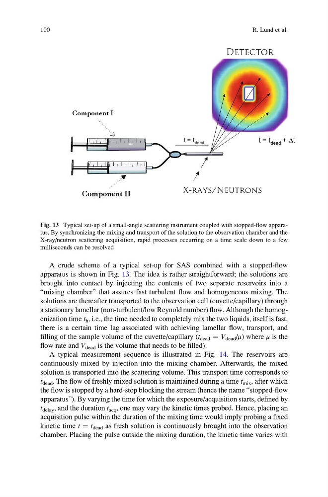
A crude scheme of a typical set-up for SAS combined with a stopped-flow
apparatus is shown in Fig. 13. The idea is rather straightforward; the solutions are
brought into contact by injecting the contents of two separate reservoirs into a
“mixing chamber” that assures fast turbulent flow and homogeneous mixing. The
solutions are thereafter transported to the observation cell (cuvette/capillary) through
a stationary lamellar (non-turbulent/low Reynold number) flow. Although the homogenization time t h , i.e., the time needed to completely mix the two liquids, itself is fast,
there is a certain time lag associated with achieving lamellar flow, transport, and
filling of the sample volume of the cuvette/capillary (t dead ¼ V dead /μ) where μ is the
flow rate and V dead is the volume that needs to be filled).
A typical measurement sequence is illustrated in Fig. 14. The reservoirs are
continuously mixed by injection into the mixing chamber. Afterwards, the mixed
solution is transported into the scattering volume. This transport time corresponds to
t dead . The flow of freshly mixed solution is maintained during a time t mix , after which
the flow is stopped by a hard-stop blocking the stream (hence the name “stopped-flow
apparatus”). By varying the time for which the exposure/acquisition starts, defined by
t delay , and the duration t acq , one may vary the kinetic times probed. Hence, placing an
acquisition pulse within the duration of the mixing time would imply probing a fixed
kinetic time t ¼ t dead as fresh solution is continuously brought into the observation
chamber. Placing the pulse outside the mixing duration, the kinetic time varies with
Fig. 13 Typical set-up of a small-angle scattering instrument coupled with stopped-flow apparatus. By synchronizing the mixing and transport of the solution to the observation chamber and the
X-ray/neutron scattering acquisition, rapid processes occurring on a time scale down to a few
milliseconds can be resolved
100
R. Lund et al.
apparatus is shown in Fig. 13. The idea is rather straightforward; the solutions are
brought into contact by injecting the contents of two separate reservoirs into a
“mixing chamber” that assures fast turbulent flow and homogeneous mixing. The
solutions are thereafter transported to the observation cell (cuvette/capillary) through
a stationary lamellar (non-turbulent/low Reynold number) flow. Although the homogenization time t h , i.e., the time needed to completely mix the two liquids, itself is fast,
there is a certain time lag associated with achieving lamellar flow, transport, and
filling of the sample volume of the cuvette/capillary (t dead ¼ V dead /μ) where μ is the
flow rate and V dead is the volume that needs to be filled).
A typical measurement sequence is illustrated in Fig. 14. The reservoirs are
continuously mixed by injection into the mixing chamber. Afterwards, the mixed
solution is transported into the scattering volume. This transport time corresponds to
t dead . The flow of freshly mixed solution is maintained during a time t mix , after which
the flow is stopped by a hard-stop blocking the stream (hence the name “stopped-flow
apparatus”). By varying the time for which the exposure/acquisition starts, defined by
t delay , and the duration t acq , one may vary the kinetic times probed. Hence, placing an
acquisition pulse within the duration of the mixing time would imply probing a fixed
kinetic time t ¼ t dead as fresh solution is continuously brought into the observation
chamber. Placing the pulse outside the mixing duration, the kinetic time varies with
Fig. 13 Typical set-up of a small-angle scattering instrument coupled with stopped-flow apparatus. By synchronizing the mixing and transport of the solution to the observation chamber and the
X-ray/neutron scattering acquisition, rapid processes occurring on a time scale down to a few
milliseconds can be resolved
100
R. Lund et al.