

5.1 Reactor Setup
83
the biofilm surface, i.e., perspex sheets. A common 10 mm dia PVC pipe was fitted
at top of the junction box through which the aeration was provided to the reactor
prior to distribution through nine (9) nos of vertical pipes. One inlet CPVC pipe of
10 mm diameter and one outlet CPVC pipe of the same diameter were connected in
the reactor in opposite direction to each other. One sludge outlet perpendicular to the
direction of inlet–outlet line was at bottom of the reactor with a stopper as shown in
Fig. 5.3.
One outlet pipe emerging from the reactor was extended to the secondary clarifier
(PVC made, 5.5-L capacity) which was placed in a PVC made tub for collecting the
overflow from the secondary clarifier. One outlet was also connected at the bottom of
the tub for discharging the effluent from the system. The reactor was allowed to run
by means of peristaltic pump as per HRT provided until quasi-steady-state condition
reached. An air pump (maximum capacity 50 lpm) was used for providing aeration
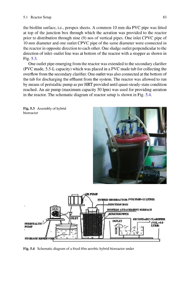
in the reactor. The schematic diagram of reactor setup is shown in Fig. 5.4.
Fig. 5.3 Assembly of hybrid
bioreactor
Fig. 5.4 Schematic diagram of a fixed film aerobic hybrid bioreactor under
83
the biofilm surface, i.e., perspex sheets. A common 10 mm dia PVC pipe was fitted
at top of the junction box through which the aeration was provided to the reactor
prior to distribution through nine (9) nos of vertical pipes. One inlet CPVC pipe of
10 mm diameter and one outlet CPVC pipe of the same diameter were connected in
the reactor in opposite direction to each other. One sludge outlet perpendicular to the
direction of inlet–outlet line was at bottom of the reactor with a stopper as shown in
Fig. 5.3.
One outlet pipe emerging from the reactor was extended to the secondary clarifier
(PVC made, 5.5-L capacity) which was placed in a PVC made tub for collecting the
overflow from the secondary clarifier. One outlet was also connected at the bottom of
the tub for discharging the effluent from the system. The reactor was allowed to run
by means of peristaltic pump as per HRT provided until quasi-steady-state condition
reached. An air pump (maximum capacity 50 lpm) was used for providing aeration
in the reactor. The schematic diagram of reactor setup is shown in Fig. 5.4.
Fig. 5.3 Assembly of hybrid
bioreactor
Fig. 5.4 Schematic diagram of a fixed film aerobic hybrid bioreactor under