

14
2 Advantages of Hybrid Bioreactor
2.2.3 Integrated Fixed-Film Activated Sludge (IFAS) System
Work on this system was first started in the 80 s and 90 s in the USA. IFAS system
adds the benefits of fixed film systems into the suspended-growth activated sludge
process. ASP has process flexibility and provides a high degree of treatment, whereas
fixed-film processes are inherently stable and resistant to organic and hydraulic shock
loading [27, 28]. The capacity of existing ASP system can be enhanced by IFAS
process without additional tankage. Two types of media like “dispersed media” and
“fixed media” were used in this system. The materials used for the attachment surface
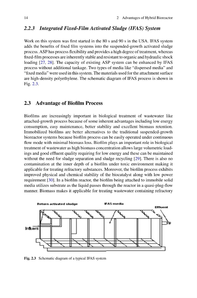
are high-density polyethylene. The schematic diagram of IFAS process is shown in
Fig. 2.3.
2.3 Advantage of Biofilm Process
Biofilms are increasingly important in biological treatment of wastewater like
attached-growth process because of some inherent advantages including low energy
consumption, easy maintenance, better stability and excellent biomass retention.
Immobilized biofilms are better alternatives to the traditional suspended-growth
bioreactor systems because biofilm process can be easily operated under continuous
flow mode with minimal biomass loss. Biofilm plays an important role in biological
treatment of wastewater as high biomass concentration allows large volumetric loadings and good effluent quality requiring for low energy and these can be maintained
without the need for sludge separation and sludge recycling [29]. There is also no
contamination at the inner depth of a biofilm under toxic environment making it
applicable for treating refractory substances. Moreover, the biofilm process exhibits
improved physical and chemical stability of the biocatalyst along with low power
requirement [30]. In a biofilm reactor, the biofilm being attached to immobile solid
media utilizes substrate as the liquid passes through the reactor in a quasi-plug-flow
manner. Biomass makes it applicable for treating wastewater containing refractory
Fig. 2.3 Schematic diagram of a typical IFAS system
2 Advantages of Hybrid Bioreactor
2.2.3 Integrated Fixed-Film Activated Sludge (IFAS) System
Work on this system was first started in the 80 s and 90 s in the USA. IFAS system
adds the benefits of fixed film systems into the suspended-growth activated sludge
process. ASP has process flexibility and provides a high degree of treatment, whereas
fixed-film processes are inherently stable and resistant to organic and hydraulic shock
loading [27, 28]. The capacity of existing ASP system can be enhanced by IFAS
process without additional tankage. Two types of media like “dispersed media” and
“fixed media” were used in this system. The materials used for the attachment surface
are high-density polyethylene. The schematic diagram of IFAS process is shown in
Fig. 2.3.
2.3 Advantage of Biofilm Process
Biofilms are increasingly important in biological treatment of wastewater like
attached-growth process because of some inherent advantages including low energy
consumption, easy maintenance, better stability and excellent biomass retention.
Immobilized biofilms are better alternatives to the traditional suspended-growth
bioreactor systems because biofilm process can be easily operated under continuous
flow mode with minimal biomass loss. Biofilm plays an important role in biological
treatment of wastewater as high biomass concentration allows large volumetric loadings and good effluent quality requiring for low energy and these can be maintained
without the need for sludge separation and sludge recycling [29]. There is also no
contamination at the inner depth of a biofilm under toxic environment making it
applicable for treating refractory substances. Moreover, the biofilm process exhibits
improved physical and chemical stability of the biocatalyst along with low power
requirement [30]. In a biofilm reactor, the biofilm being attached to immobile solid
media utilizes substrate as the liquid passes through the reactor in a quasi-plug-flow
manner. Biomass makes it applicable for treating wastewater containing refractory
Fig. 2.3 Schematic diagram of a typical IFAS system