

8.5 Process Design Approach for Fixed-Bed Hybrid Bioreactor
119
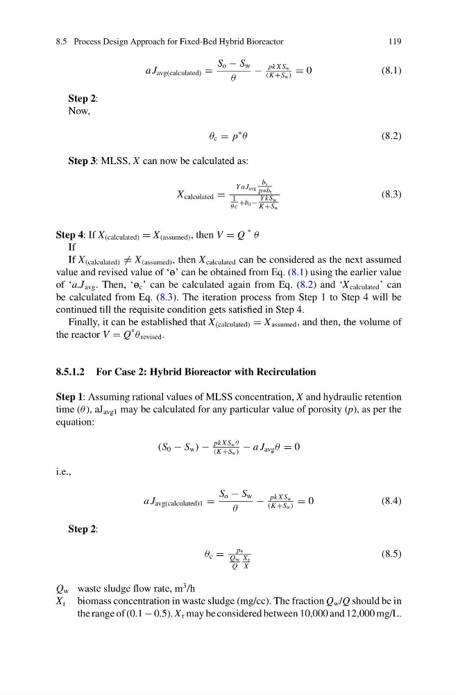
a J avg(calculated) =
S o − S w
θ
−
pk X S w
(K +S w )
= 0
(8.1)
Step 2:
Now,
θ c = p
∗
θ
(8.2)
Step 3: MLSS, X can now be calculated as:
X calculated =
Y a J avg
b s
p∗b t
1
θc
+b d −
Y kS w
K +S w
(8.3)
Step 4: If X (calculated) = X (assumed) , then V = Q
*
θ
If
If X (calculated) = X (assumed) , then X calculated can be considered as the next assumed
value and revised value of ‘P’ can be obtained from Eq. (8.1) using the earlier value
of ‘a.J avg . Then, ‘P c ’ can be calculated again from Eq. (8.2) and ‘X calculated ’ can
be calculated from Eq. (8.3). The iteration process from Step 1 to Step 4 will be
continued till the requisite condition gets satisfied in Step 4.
Finally, it can be established that X (calculated) = X assumed , and then, the volume of
the reactor V = Q
*
θ revised .
8.5.1.2 For Case 2: Hybrid Bioreactor with Recirculation
Step 1: Assuming rational values of MLSS concentration, X and hydraulic retention
time (θ ), aJ avg1 may be calculated for any particular value of porosity (p), as per the
equation:
(S 0 − S w ) −
pk X S w θ
(K +S w )
− a J avg θ = 0
i.e.,
a J avg(calculated)1 =
S o − S w
θ
−
pk X S w
(K +S w )
= 0
( 8 . 4 )
Step 2:
θ c =
p θ
Q w
Q
X r
X
(8.5)
Q w waste sludge flow rate, m
3 /h
X r biomass concentration in waste sludge (mg/cc). The fraction Q w /Q should be in
the range of (0.1 − 0.5). X r may be considered between 10,000 and 12,000 mg/L.
119
a J avg(calculated) =
S o − S w
θ
−
pk X S w
(K +S w )
= 0
(8.1)
Step 2:
Now,
θ c = p
∗
θ
(8.2)
Step 3: MLSS, X can now be calculated as:
X calculated =
Y a J avg
b s
p∗b t
1
θc
+b d −
Y kS w
K +S w
(8.3)
Step 4: If X (calculated) = X (assumed) , then V = Q
*
θ
If
If X (calculated) = X (assumed) , then X calculated can be considered as the next assumed
value and revised value of ‘P’ can be obtained from Eq. (8.1) using the earlier value
of ‘a.J avg . Then, ‘P c ’ can be calculated again from Eq. (8.2) and ‘X calculated ’ can
be calculated from Eq. (8.3). The iteration process from Step 1 to Step 4 will be
continued till the requisite condition gets satisfied in Step 4.
Finally, it can be established that X (calculated) = X assumed , and then, the volume of
the reactor V = Q
*
θ revised .
8.5.1.2 For Case 2: Hybrid Bioreactor with Recirculation
Step 1: Assuming rational values of MLSS concentration, X and hydraulic retention
time (θ ), aJ avg1 may be calculated for any particular value of porosity (p), as per the
equation:
(S 0 − S w ) −
pk X S w θ
(K +S w )
− a J avg θ = 0
i.e.,
a J avg(calculated)1 =
S o − S w
θ
−
pk X S w
(K +S w )
= 0
( 8 . 4 )
Step 2:
θ c =
p θ
Q w
Q
X r
X
(8.5)
Q w waste sludge flow rate, m
3 /h
X r biomass concentration in waste sludge (mg/cc). The fraction Q w /Q should be in
the range of (0.1 − 0.5). X r may be considered between 10,000 and 12,000 mg/L.