

206
A. Rabiei et al.
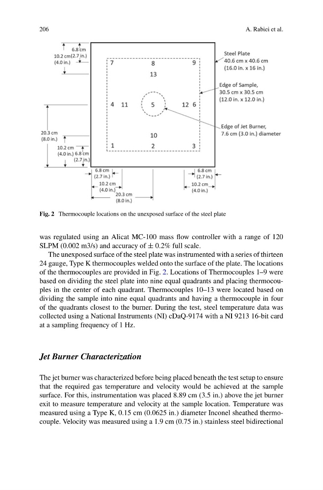
Fig. 2 Thermocouple locations on the unexposed surface of the steel plate
was regulated using an Alicat MC-100 mass flow controller with a range of 120
SLPM (0.002 m3/s) and accuracy of ± 0.2% full scale.
The unexposed surface of the steel plate was instrumented with a series of thirteen
24 gauge, Type K thermocouples welded onto the surface of the plate. The locations
of the thermocouples are provided in Fig. 2. Locations of Thermocouples 1–9 were
based on dividing the steel plate into nine equal quadrants and placing thermocouples in the center of each quadrant. Thermocouples 10–13 were located based on
dividing the sample into nine equal quadrants and having a thermocouple in four
of the quadrants closest to the burner. During the test, steel temperature data was
collected using a National Instruments (NI) cDaQ-9174 with a NI 9213 16-bit card
at a sampling frequency of 1 Hz.
Jet Burner Characterization
The jet burner was characterized before being placed beneath the test setup to ensure
that the required gas temperature and velocity would be achieved at the sample
surface. For this, instrumentation was placed 8.89 cm (3.5 in.) above the jet burner
exit to measure temperature and velocity at the sample location. Temperature was
measured using a Type K, 0.15 cm (0.0625 in.) diameter Inconel sheathed thermocouple. Velocity was measured using a 1.9 cm (0.75 in.) stainless steel bidirectional
A. Rabiei et al.
Fig. 2 Thermocouple locations on the unexposed surface of the steel plate
was regulated using an Alicat MC-100 mass flow controller with a range of 120
SLPM (0.002 m3/s) and accuracy of ± 0.2% full scale.
The unexposed surface of the steel plate was instrumented with a series of thirteen
24 gauge, Type K thermocouples welded onto the surface of the plate. The locations
of the thermocouples are provided in Fig. 2. Locations of Thermocouples 1–9 were
based on dividing the steel plate into nine equal quadrants and placing thermocouples in the center of each quadrant. Thermocouples 10–13 were located based on
dividing the sample into nine equal quadrants and having a thermocouple in four
of the quadrants closest to the burner. During the test, steel temperature data was
collected using a National Instruments (NI) cDaQ-9174 with a NI 9213 16-bit card
at a sampling frequency of 1 Hz.
Jet Burner Characterization
The jet burner was characterized before being placed beneath the test setup to ensure
that the required gas temperature and velocity would be achieved at the sample
surface. For this, instrumentation was placed 8.89 cm (3.5 in.) above the jet burner
exit to measure temperature and velocity at the sample location. Temperature was
measured using a Type K, 0.15 cm (0.0625 in.) diameter Inconel sheathed thermocouple. Velocity was measured using a 1.9 cm (0.75 in.) stainless steel bidirectional