

A Comparative Study on the Effect of Graphene and Multi-walled …
157
Weld Strengthening Mechanisms
The results obtained from the study suggest that an enhanced mechanical rapheme
due to the incorporation of rapheme nanoplatelets/multi-walled carbon nanotubes
interlayers has been observed. Generally, whenever a carbonaceous nanomaterial
(GNPS/MWCNTS) is added to the weld pool (Fe matrix), a Fe–C nanocomposite is
made at the weld nugget zone. The load transfer efficiency from the Fe matrix to the
carbonaceous nanomaterials which acts as reinforcements also affects the strength
of the nanocomposite. Several mechanisms act together or individually to improve
the weld strength of the nanocomposite developed in the weld nugget area in case
of resistance spot welding which are grain refinement, dislocation density enhancement at the grain boundaries owing to the thermal mismatch and effective matrixreinforcement load transmission [25]. The differences in the coefficients of thermal
expansion (CTE) of the matrix (Fe) and the reinforcements (GNPs/MWCNTs) cause
the prismatic pinning of the dislocation movement at the reinforcement interfaces
and the matrix (steel). The incorporated reinforcements’ surface area also plays a
vital character in the increase of the dislocation density which has an inverse relation
to the grain size [40]. The enhancement in the strength of the composite by the grain
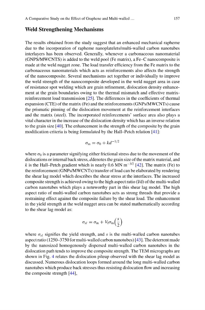
modification criteria is being formulated by the Hall–Petch relation [41]:
σ m = σ 0 + kd
−1/2
where σ 0 is a parameter signifying either frictional stress due to the movement of the
dislocations or internal back stress, ddenotes the grain size of the matrix material, and
k is the Hall–Petch gradient which is nearly 0.6 MN m
−3/2 [42]. The matrix (Fe) to
the reinforcement (GNPs/MWCNTs) transfer of load can be elaborated by rendering
the shear lag model which describes the shear stress at the interfaces. The increased
composite strength is achieved owing to the high aspect ratio (l/d) of the multi-walled
carbon nanotubes which plays a noteworthy part in this shear lag model. The high
aspect ratio of multi-walled carbon nanotubes acts as strong threads that provide a
restraining effect against the composite failure by the shear load. The enhancement
in the yield strength at the weld nugget area can be stated mathematically according
to the shear lag model as:
σ sl = σ m + V f σ m
s
2
where σ sl signifies the yield strength, and s is the multi-walled carbon nanotubes
aspect ratio (1250–3750 for multi-walled carbon nanotubes) [43]. The deterrent made
by the nanosized homogenously dispersed multi-walled carbon nanotubes in the
dislocation path tends to improve the composite strength. The TEM micrographs are
shown in Fig. 4 relates the dislocation pileup observed with the shear lag model as
discussed. Numerous dislocation loops formed around the long multi-walled carbon
nanotubes which produce back stresses thus resisting dislocation flow and increasing
the composite strength [44],
157
Weld Strengthening Mechanisms
The results obtained from the study suggest that an enhanced mechanical rapheme
due to the incorporation of rapheme nanoplatelets/multi-walled carbon nanotubes
interlayers has been observed. Generally, whenever a carbonaceous nanomaterial
(GNPS/MWCNTS) is added to the weld pool (Fe matrix), a Fe–C nanocomposite is
made at the weld nugget zone. The load transfer efficiency from the Fe matrix to the
carbonaceous nanomaterials which acts as reinforcements also affects the strength
of the nanocomposite. Several mechanisms act together or individually to improve
the weld strength of the nanocomposite developed in the weld nugget area in case
of resistance spot welding which are grain refinement, dislocation density enhancement at the grain boundaries owing to the thermal mismatch and effective matrixreinforcement load transmission [25]. The differences in the coefficients of thermal
expansion (CTE) of the matrix (Fe) and the reinforcements (GNPs/MWCNTs) cause
the prismatic pinning of the dislocation movement at the reinforcement interfaces
and the matrix (steel). The incorporated reinforcements’ surface area also plays a
vital character in the increase of the dislocation density which has an inverse relation
to the grain size [40]. The enhancement in the strength of the composite by the grain
modification criteria is being formulated by the Hall–Petch relation [41]:
σ m = σ 0 + kd
−1/2
where σ 0 is a parameter signifying either frictional stress due to the movement of the
dislocations or internal back stress, ddenotes the grain size of the matrix material, and
k is the Hall–Petch gradient which is nearly 0.6 MN m
−3/2 [42]. The matrix (Fe) to
the reinforcement (GNPs/MWCNTs) transfer of load can be elaborated by rendering
the shear lag model which describes the shear stress at the interfaces. The increased
composite strength is achieved owing to the high aspect ratio (l/d) of the multi-walled
carbon nanotubes which plays a noteworthy part in this shear lag model. The high
aspect ratio of multi-walled carbon nanotubes acts as strong threads that provide a
restraining effect against the composite failure by the shear load. The enhancement
in the yield strength at the weld nugget area can be stated mathematically according
to the shear lag model as:
σ sl = σ m + V f σ m
s
2
where σ sl signifies the yield strength, and s is the multi-walled carbon nanotubes
aspect ratio (1250–3750 for multi-walled carbon nanotubes) [43]. The deterrent made
by the nanosized homogenously dispersed multi-walled carbon nanotubes in the
dislocation path tends to improve the composite strength. The TEM micrographs are
shown in Fig. 4 relates the dislocation pileup observed with the shear lag model as
discussed. Numerous dislocation loops formed around the long multi-walled carbon
nanotubes which produce back stresses thus resisting dislocation flow and increasing
the composite strength [44],