

74
3 Physical Theory of RFID System Physical Anti-Collision
to simulate the environment of a blood bank. The research demonstrated that the
reading ability of RFID tags could be affected under extreme conditions.
Due to the advantages of the UHF RFID system, it can be used in special environments, including high temperature or high humidity environments like deserts
and lakes. Yu et al. [25] designed a testing platform for the evaluation of UHF RFID
tags’ performance at different temperatures. Whether the harsh environments will
have an influence on the tag’s performance has become an important issue in tag
improvement research. In past studies, it has been analyzed from the perspective of
temperature influence, but few studies have been done from a humidity perspective.
In this chapter, the semi-physical simulation of the humidity environment simulates
the gradual process from low humidity to high humidity. Furthermore, the humidity
influence theory is proposed, which is of great significance for the study of UHF
RFID tag performance.
(1) Fundamental principle
Electromagnetic waves are emitted from the antenna to the surrounding space and
encounter different targets. Part of the electromagnetic energy reaching these targets
is absorbed and the other part is scattered in various directions with different intensities. A portion of the reflected energy is eventually returned to the transmitting
antenna.
For reflective scattering RFID systems, the tag uses electromagnetic reflected
waves to complete the energy transfer from the tag to the reader. Its energy
transmission process can be divided into forward link and reverse link transmission.
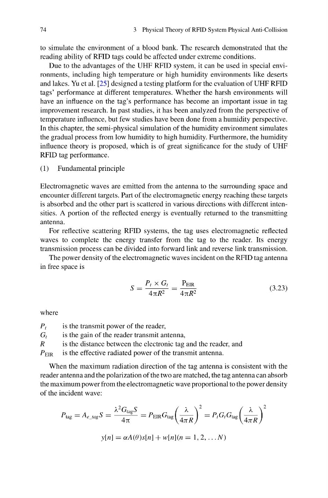
The power density of the electromagnetic waves incident on the RFID tag antenna
in free space is
S =
P t × G t
4πR 2 =
P EIR
4πR 2
(3.23)
where
P t
is the transmit power of the reader,
G t
is the gain of the reader transmit antenna,
R
is the distance between the electronic tag and the reader, and
P EIR is the effective radiated power of the transmit antenna.
When the maximum radiation direction of the tag antenna is consistent with the
reader antenna and the polarization of the two are matched, the tag antenna can absorb
the maximum power from the electromagnetic wave proportional to the power density
of the incident wave:
P tag = A e_tag S =
λ
2 G tag S
4π
= P EIR G tag
λ
4π R
2
= P t G t G tag
λ
4π R
2
y[n] = αA(θ )s[n] + w[n](n = 1, 2, . . . N )
3 Physical Theory of RFID System Physical Anti-Collision
to simulate the environment of a blood bank. The research demonstrated that the
reading ability of RFID tags could be affected under extreme conditions.
Due to the advantages of the UHF RFID system, it can be used in special environments, including high temperature or high humidity environments like deserts
and lakes. Yu et al. [25] designed a testing platform for the evaluation of UHF RFID
tags’ performance at different temperatures. Whether the harsh environments will
have an influence on the tag’s performance has become an important issue in tag
improvement research. In past studies, it has been analyzed from the perspective of
temperature influence, but few studies have been done from a humidity perspective.
In this chapter, the semi-physical simulation of the humidity environment simulates
the gradual process from low humidity to high humidity. Furthermore, the humidity
influence theory is proposed, which is of great significance for the study of UHF
RFID tag performance.
(1) Fundamental principle
Electromagnetic waves are emitted from the antenna to the surrounding space and
encounter different targets. Part of the electromagnetic energy reaching these targets
is absorbed and the other part is scattered in various directions with different intensities. A portion of the reflected energy is eventually returned to the transmitting
antenna.
For reflective scattering RFID systems, the tag uses electromagnetic reflected
waves to complete the energy transfer from the tag to the reader. Its energy
transmission process can be divided into forward link and reverse link transmission.
The power density of the electromagnetic waves incident on the RFID tag antenna
in free space is
S =
P t × G t
4πR 2 =
P EIR
4πR 2
(3.23)
where
P t
is the transmit power of the reader,
G t
is the gain of the reader transmit antenna,
R
is the distance between the electronic tag and the reader, and
P EIR is the effective radiated power of the transmit antenna.
When the maximum radiation direction of the tag antenna is consistent with the
reader antenna and the polarization of the two are matched, the tag antenna can absorb
the maximum power from the electromagnetic wave proportional to the power density
of the incident wave:
P tag = A e_tag S =
λ
2 G tag S
4π
= P EIR G tag
λ
4π R
2
= P t G t G tag
λ
4π R
2
y[n] = αA(θ )s[n] + w[n](n = 1, 2, . . . N )