

3.1 Thermodynamic Analysis of Physical Anti-Collision …
67
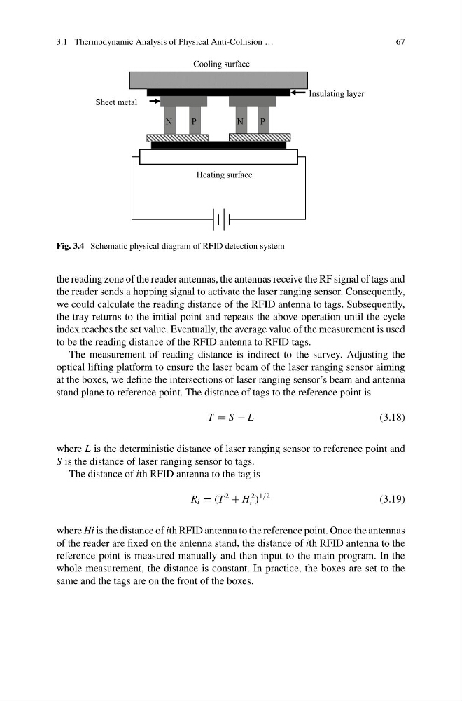
Fig. 3.4 Schematic physical diagram of RFID detection system
the reading zone of the reader antennas, the antennas receive the RF signal of tags and
the reader sends a hopping signal to activate the laser ranging sensor. Consequently,
we could calculate the reading distance of the RFID antenna to tags. Subsequently,
the tray returns to the initial point and repeats the above operation until the cycle
index reaches the set value. Eventually, the average value of the measurement is used
to be the reading distance of the RFID antenna to RFID tags.
The measurement of reading distance is indirect to the survey. Adjusting the
optical lifting platform to ensure the laser beam of the laser ranging sensor aiming
at the boxes, we define the intersections of laser ranging sensor’s beam and antenna
stand plane to reference point. The distance of tags to the reference point is
T = S − L
(3.18)
where L is the deterministic distance of laser ranging sensor to reference point and
S is the distance of laser ranging sensor to tags.
The distance of ith RFID antenna to the tag is
R i = (T
2
+ H
2
i )
1/2
(3.19)
where Hi is the distance of ith RFID antenna to the reference point. Once the antennas
of the reader are fixed on the antenna stand, the distance of ith RFID antenna to the
reference point is measured manually and then input to the main program. In the
whole measurement, the distance is constant. In practice, the boxes are set to the
same and the tags are on the front of the boxes.
67
Fig. 3.4 Schematic physical diagram of RFID detection system
the reading zone of the reader antennas, the antennas receive the RF signal of tags and
the reader sends a hopping signal to activate the laser ranging sensor. Consequently,
we could calculate the reading distance of the RFID antenna to tags. Subsequently,
the tray returns to the initial point and repeats the above operation until the cycle
index reaches the set value. Eventually, the average value of the measurement is used
to be the reading distance of the RFID antenna to RFID tags.
The measurement of reading distance is indirect to the survey. Adjusting the
optical lifting platform to ensure the laser beam of the laser ranging sensor aiming
at the boxes, we define the intersections of laser ranging sensor’s beam and antenna
stand plane to reference point. The distance of tags to the reference point is
T = S − L
(3.18)
where L is the deterministic distance of laser ranging sensor to reference point and
S is the distance of laser ranging sensor to tags.
The distance of ith RFID antenna to the tag is
R i = (T
2
+ H
2
i )
1/2
(3.19)
where Hi is the distance of ith RFID antenna to the reference point. Once the antennas
of the reader are fixed on the antenna stand, the distance of ith RFID antenna to the
reference point is measured manually and then input to the main program. In the
whole measurement, the distance is constant. In practice, the boxes are set to the
same and the tags are on the front of the boxes.