

6.4 Multi-level Wavelet CNN for Image Restoration in Pre-Processing Sub-System
223
6.4.4 Network Architecture
The key of network structure design in this paper is the design of CNN after DWT. In
this paper, we use a four-layer FCN without a pool as the CNN module. At the same
time, CNN is deployed in high-frequency and low-frequency sub-bands of different
layers. After DWT transform, there is a certain correlation between different subbands. Therefore, CNN after DWT can make full use of the nonlinear characteristics
of CNN to extract effective features, and suppress the correlation between each subband. In this paper, the CNN sub-block consists of three parts: 3*3 convolutional
filter (Conv), batch normalization (BN), and rectifier linear unit (ReLU). For the last
layer of CNN, only Conv term is retained to predict the residual image.
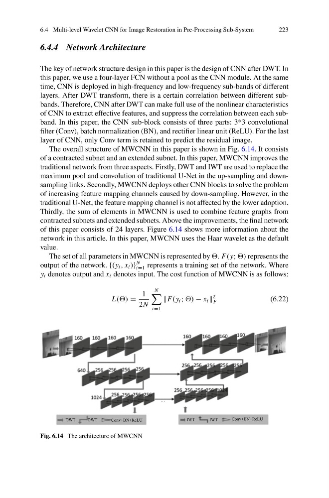
The overall structure of MWCNN in this paper is shown in Fig. 6.14. It consists
of a contracted subnet and an extended subnet. In this paper, MWCNN improves the
traditional network from three aspects. Firstly, DWT and IWT are used to replace the
maximum pool and convolution of traditional U-Net in the up-sampling and downsampling links. Secondly, MWCNN deploys other CNN blocks to solve the problem
of increasing feature mapping channels caused by down-sampling. However, in the
traditional U-Net, the feature mapping channel is not affected by the lower adoption.
Thirdly, the sum of elements in MWCNN is used to combine feature graphs from
contracted subnets and extended subnets. Above the improvements, the final network
of this paper consists of 24 layers. Figure 6.14 shows more information about the
network in this article. In this paper, MWCNN uses the Haar wavelet as the default
value.
The set of all parameters in MWCNN is represented by F(y; ) represents the
output of the network. {(y i , x i )}
N
i=1 represents a training set of the network. Where
y i denotes output and x i denotes input. The cost function of MWCNN is as follows:
L(() =
1
2N
N
i=1
F(y i ; − x i
2
F
(6.22)
Fig. 6.14 The architecture of MWCNN
223
6.4.4 Network Architecture
The key of network structure design in this paper is the design of CNN after DWT. In
this paper, we use a four-layer FCN without a pool as the CNN module. At the same
time, CNN is deployed in high-frequency and low-frequency sub-bands of different
layers. After DWT transform, there is a certain correlation between different subbands. Therefore, CNN after DWT can make full use of the nonlinear characteristics
of CNN to extract effective features, and suppress the correlation between each subband. In this paper, the CNN sub-block consists of three parts: 3*3 convolutional
filter (Conv), batch normalization (BN), and rectifier linear unit (ReLU). For the last
layer of CNN, only Conv term is retained to predict the residual image.
The overall structure of MWCNN in this paper is shown in Fig. 6.14. It consists
of a contracted subnet and an extended subnet. In this paper, MWCNN improves the
traditional network from three aspects. Firstly, DWT and IWT are used to replace the
maximum pool and convolution of traditional U-Net in the up-sampling and downsampling links. Secondly, MWCNN deploys other CNN blocks to solve the problem
of increasing feature mapping channels caused by down-sampling. However, in the
traditional U-Net, the feature mapping channel is not affected by the lower adoption.
Thirdly, the sum of elements in MWCNN is used to combine feature graphs from
contracted subnets and extended subnets. Above the improvements, the final network
of this paper consists of 24 layers. Figure 6.14 shows more information about the
network in this article. In this paper, MWCNN uses the Haar wavelet as the default
value.
The set of all parameters in MWCNN is represented by F(y; ) represents the
output of the network. {(y i , x i )}
N
i=1 represents a training set of the network. Where
y i denotes output and x i denotes input. The cost function of MWCNN is as follows:
L(() =
1
2N
N
i=1
F(y i ; − x i
2
F
(6.22)
Fig. 6.14 The architecture of MWCNN