

204
6 Deep Learning and RFID System Physical Anti-Collision
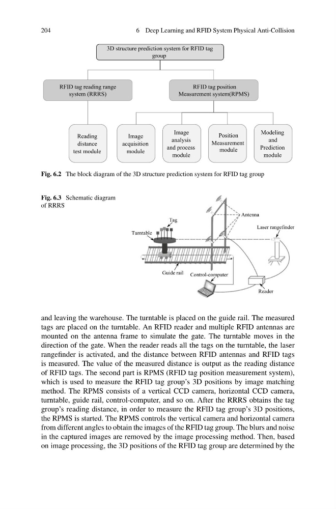
Fig. 6.2 The block diagram of the 3D structure prediction system for RFID tag group
Fig. 6.3 Schematic diagram
of RRRS
and leaving the warehouse. The turntable is placed on the guide rail. The measured
tags are placed on the turntable. An RFID reader and multiple RFID antennas are
mounted on the antenna frame to simulate the gate. The turntable moves in the
direction of the gate. When the reader reads all the tags on the turntable, the laser
rangefinder is activated, and the distance between RFID antennas and RFID tags
is measured. The value of the measured distance is output as the reading distance
of RFID tags. The second part is RPMS (RFID tag position measurement system),
which is used to measure the RFID tag group’s 3D positions by image matching
method. The RPMS consists of a vertical CCD camera, horizontal CCD camera,
turntable, guide rail, control-computer, and so on. After the RRRS obtains the tag
group’s reading distance, in order to measure the RFID tag group’s 3D positions,
the RPMS is started. The RPMS controls the vertical camera and horizontal camera
from different angles to obtain the images of the RFID tag group. The blurs and noise
in the captured images are removed by the image processing method. Then, based
on image processing, the 3D positions of the RFID tag group are determined by the
6 Deep Learning and RFID System Physical Anti-Collision
Fig. 6.2 The block diagram of the 3D structure prediction system for RFID tag group
Fig. 6.3 Schematic diagram
of RRRS
and leaving the warehouse. The turntable is placed on the guide rail. The measured
tags are placed on the turntable. An RFID reader and multiple RFID antennas are
mounted on the antenna frame to simulate the gate. The turntable moves in the
direction of the gate. When the reader reads all the tags on the turntable, the laser
rangefinder is activated, and the distance between RFID antennas and RFID tags
is measured. The value of the measured distance is output as the reading distance
of RFID tags. The second part is RPMS (RFID tag position measurement system),
which is used to measure the RFID tag group’s 3D positions by image matching
method. The RPMS consists of a vertical CCD camera, horizontal CCD camera,
turntable, guide rail, control-computer, and so on. After the RRRS obtains the tag
group’s reading distance, in order to measure the RFID tag group’s 3D positions,
the RPMS is started. The RPMS controls the vertical camera and horizontal camera
from different angles to obtain the images of the RFID tag group. The blurs and noise
in the captured images are removed by the image processing method. Then, based
on image processing, the 3D positions of the RFID tag group are determined by the