

190
5 Optimization Algorithm and RFID System Physical Anti-Collision
Fig. 5.29 Diagram of center
location of turntable
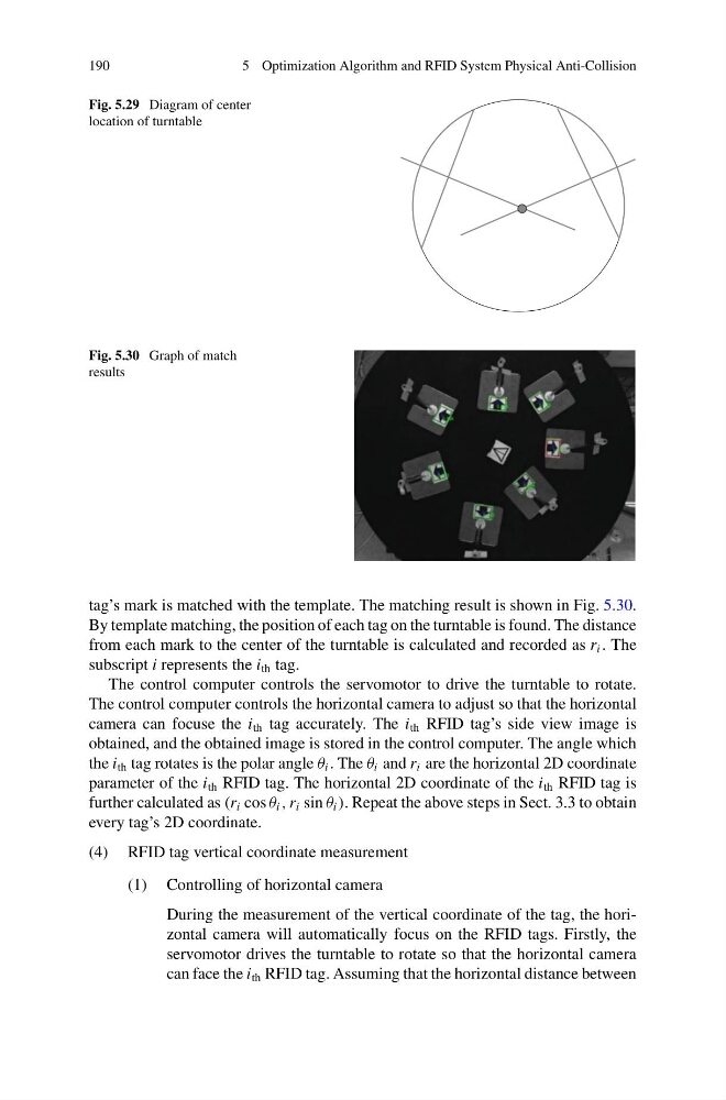
Fig. 5.30 Graph of match
results
tag’s mark is matched with the template. The matching result is shown in Fig. 5.30.
By template matching, the position of each tag on the turntable is found. The distance
from each mark to the center of the turntable is calculated and recorded as r i . The
subscript i represents the i th tag.
The control computer controls the servomotor to drive the turntable to rotate.
The control computer controls the horizontal camera to adjust so that the horizontal
camera can focuse the i th tag accurately. The i th RFID tag’s side view image is
obtained, and the obtained image is stored in the control computer. The angle which
the i th tag rotates is the polar angle θ i . The θ i and r i are the horizontal 2D coordinate
parameter of the i th RFID tag. The horizontal 2D coordinate of the i th RFID tag is
further calculated as (r i cos θ i , r i sin θ i ). Repeat the above steps in Sect. 3.3 to obtain
every tag’s 2D coordinate.
(4) RFID tag vertical coordinate measurement
(1) Controlling of horizontal camera
During the measurement of the vertical coordinate of the tag, the horizontal camera will automatically focus on the RFID tags. Firstly, the
servomotor drives the turntable to rotate so that the horizontal camera
can face the i th RFID tag. Assuming that the horizontal distance between
5 Optimization Algorithm and RFID System Physical Anti-Collision
Fig. 5.29 Diagram of center
location of turntable
Fig. 5.30 Graph of match
results
tag’s mark is matched with the template. The matching result is shown in Fig. 5.30.
By template matching, the position of each tag on the turntable is found. The distance
from each mark to the center of the turntable is calculated and recorded as r i . The
subscript i represents the i th tag.
The control computer controls the servomotor to drive the turntable to rotate.
The control computer controls the horizontal camera to adjust so that the horizontal
camera can focuse the i th tag accurately. The i th RFID tag’s side view image is
obtained, and the obtained image is stored in the control computer. The angle which
the i th tag rotates is the polar angle θ i . The θ i and r i are the horizontal 2D coordinate
parameter of the i th RFID tag. The horizontal 2D coordinate of the i th RFID tag is
further calculated as (r i cos θ i , r i sin θ i ). Repeat the above steps in Sect. 3.3 to obtain
every tag’s 2D coordinate.
(4) RFID tag vertical coordinate measurement
(1) Controlling of horizontal camera
During the measurement of the vertical coordinate of the tag, the horizontal camera will automatically focus on the RFID tags. Firstly, the
servomotor drives the turntable to rotate so that the horizontal camera
can face the i th RFID tag. Assuming that the horizontal distance between