

5.3 Physical Anti-Collision Based on Wavelet
189
Table 5.5 Denoising results of different scenes
Original noisy
image
db2 method
sym4 method
Wiener filter
method
Median filter
method
scene 1
7.7324
16.2199
16.2746
16.0556
13.9894
scene 2
6.5652
14.0288
14.0775
13.9889
12.3192
scene 3
6.0982
14.3203
14.3815
14.0722
12.4478
scene 4
5.3621
13.7378
13.7803
13.6026
11.7055
scene 5
6.5006
14.4023
14.4536
14.3226
12.4982
scene 6
5.7315
13.7388
13.8019
13.5380
11.9579
scene 7
6.1654
14.7818
14.8242
14.6252
12.4754
scene 8
6.6532
13.8800
13.9356
13.8672
12.2909
scene 9
5.2235
12.5797
12.6294
12.4445
11.0054
scene 10
6.0594
13.8803
13.9328
13.6897
11.9642
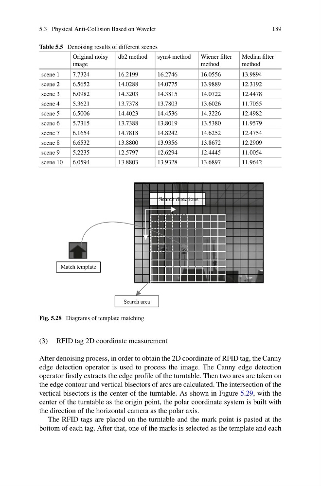
Fig. 5.28 Diagrams of template matching
(3) RFID tag 2D coordinate measurement
After denoising process, in order to obtain the 2D coordinate of RFID tag, the Canny
edge detection operator is used to process the image. The Canny edge detection
operator firstly extracts the edge profile of the turntable. Then two arcs are taken on
the edge contour and vertical bisectors of arcs are calculated. The intersection of the
vertical bisectors is the center of the turntable. As shown in Figure 5.29, with the
center of the turntable as the origin point, the polar coordinate system is built with
the direction of the horizontal camera as the polar axis.
The RFID tags are placed on the turntable and the mark point is pasted at the
bottom of each tag. After that, one of the marks is selected as the template and each
189
Table 5.5 Denoising results of different scenes
Original noisy
image
db2 method
sym4 method
Wiener filter
method
Median filter
method
scene 1
7.7324
16.2199
16.2746
16.0556
13.9894
scene 2
6.5652
14.0288
14.0775
13.9889
12.3192
scene 3
6.0982
14.3203
14.3815
14.0722
12.4478
scene 4
5.3621
13.7378
13.7803
13.6026
11.7055
scene 5
6.5006
14.4023
14.4536
14.3226
12.4982
scene 6
5.7315
13.7388
13.8019
13.5380
11.9579
scene 7
6.1654
14.7818
14.8242
14.6252
12.4754
scene 8
6.6532
13.8800
13.9356
13.8672
12.2909
scene 9
5.2235
12.5797
12.6294
12.4445
11.0054
scene 10
6.0594
13.8803
13.9328
13.6897
11.9642
Fig. 5.28 Diagrams of template matching
(3) RFID tag 2D coordinate measurement
After denoising process, in order to obtain the 2D coordinate of RFID tag, the Canny
edge detection operator is used to process the image. The Canny edge detection
operator firstly extracts the edge profile of the turntable. Then two arcs are taken on
the edge contour and vertical bisectors of arcs are calculated. The intersection of the
vertical bisectors is the center of the turntable. As shown in Figure 5.29, with the
center of the turntable as the origin point, the polar coordinate system is built with
the direction of the horizontal camera as the polar axis.
The RFID tags are placed on the turntable and the mark point is pasted at the
bottom of each tag. After that, one of the marks is selected as the template and each