

176
5 Optimization Algorithm and RFID System Physical Anti-Collision
P r x = A W S back =
P t x G t x G r x λ
2
(4π) 3 R 4 σ
(5.28)
where σ is the radar cross section of the RFID tag, G t x is the gain of the reader’s
receiving antenna, and A W is the effective area of the reader’s antenna given by
A W =
λ
2
4π
G r x
(5.29)
(4) Test process
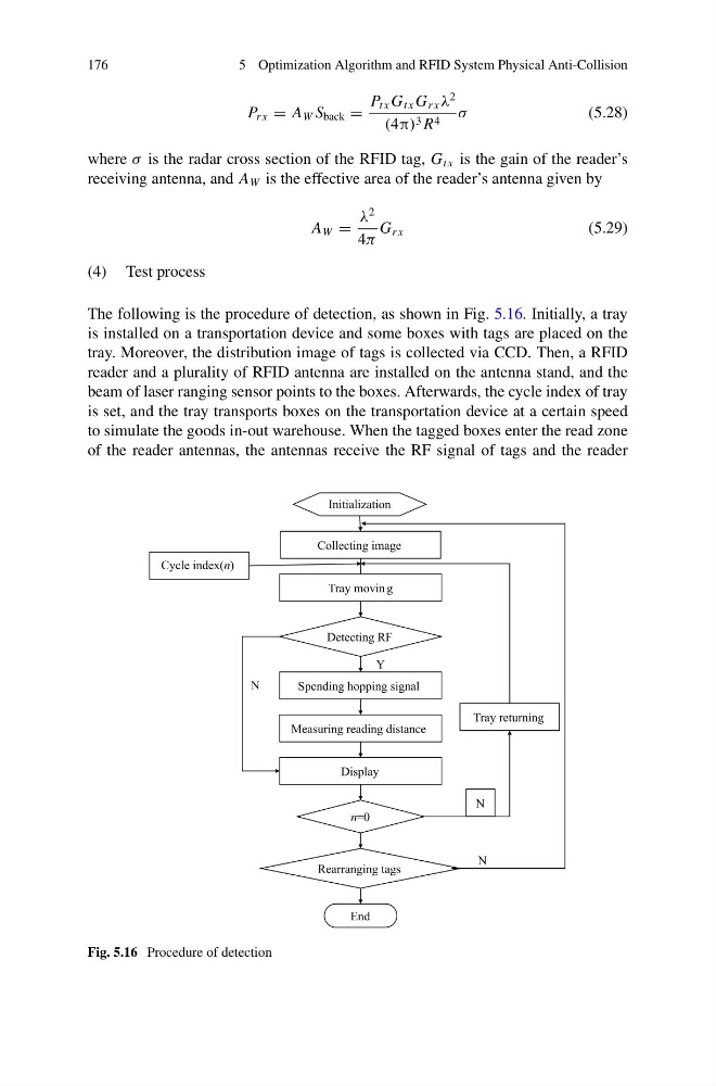
The following is the procedure of detection, as shown in Fig. 5.16. Initially, a tray
is installed on a transportation device and some boxes with tags are placed on the
tray. Moreover, the distribution image of tags is collected via CCD. Then, a RFID
reader and a plurality of RFID antenna are installed on the antenna stand, and the
beam of laser ranging sensor points to the boxes. Afterwards, the cycle index of tray
is set, and the tray transports boxes on the transportation device at a certain speed
to simulate the goods in-out warehouse. When the tagged boxes enter the read zone
of the reader antennas, the antennas receive the RF signal of tags and the reader
Fig. 5.16 Procedure of detection
5 Optimization Algorithm and RFID System Physical Anti-Collision
P r x = A W S back =
P t x G t x G r x λ
2
(4π) 3 R 4 σ
(5.28)
where σ is the radar cross section of the RFID tag, G t x is the gain of the reader’s
receiving antenna, and A W is the effective area of the reader’s antenna given by
A W =
λ
2
4π
G r x
(5.29)
(4) Test process
The following is the procedure of detection, as shown in Fig. 5.16. Initially, a tray
is installed on a transportation device and some boxes with tags are placed on the
tray. Moreover, the distribution image of tags is collected via CCD. Then, a RFID
reader and a plurality of RFID antenna are installed on the antenna stand, and the
beam of laser ranging sensor points to the boxes. Afterwards, the cycle index of tray
is set, and the tray transports boxes on the transportation device at a certain speed
to simulate the goods in-out warehouse. When the tagged boxes enter the read zone
of the reader antennas, the antennas receive the RF signal of tags and the reader
Fig. 5.16 Procedure of detection