

5.2 Physical Anti-Collision Based on Support Vector Machine (SVM)
175
The test protocol module could be simultaneously extended according
to test requirement. The test protocol module exchanges command data
with other modules to realize parameter configuration, data storage and
result shows.
(4) Storage module.
Once detection is over, the detection results are real-time shown and the
data is stored in storage module.
(3) Theoretical analysis of test
In practical application, tags are attached to the surface of targets and generate
induction current to send data due to the electromagnetic field transmitted by reader
antennas. Then, the readers detect and decode the backscattered signal of tags. Eventually, the readers send the data of tags to the background processor, and the RFID
system achieves the purpose of automatic identification of goods.
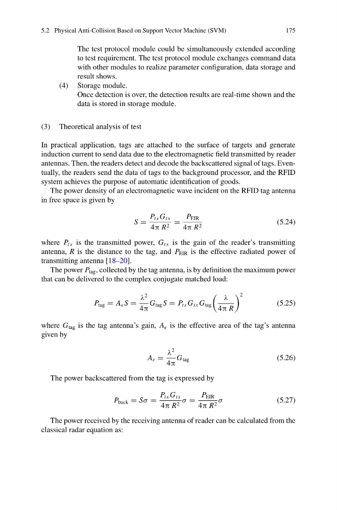
The power density of an electromagnetic wave incident on the RFID tag antenna
in free space is given by
S =
P t x G t x
4π R 2 =
P EIR
4π R 2
(5.24)
where P t x is the transmitted power, G t x is the gain of the reader’s transmitting
antenna, R is the distance to the tag, and P EIR is the effective radiated power of
transmitting antenna [18–20].
The power P tag , collected by the tag antenna, is by definition the maximum power
that can be delivered to the complex conjugate matched load:
P tag = A e S =
λ
2
4π
G tag S = P t x G t x G tag
λ
4π R
2
(5.25)
where G tag is the tag antenna’s gain, A e is the effective area of the tag’s antenna
given by
A e =
λ
2
4π
G tag
(5.26)
The power backscattered from the tag is expressed by
P back = Sσ =
P t x G t x
4π R 2 σ =
P EIR
4π R 2 σ
(5.27)
The power received by the receiving antenna of reader can be calculated from the
classical radar equation as:
175
The test protocol module could be simultaneously extended according
to test requirement. The test protocol module exchanges command data
with other modules to realize parameter configuration, data storage and
result shows.
(4) Storage module.
Once detection is over, the detection results are real-time shown and the
data is stored in storage module.
(3) Theoretical analysis of test
In practical application, tags are attached to the surface of targets and generate
induction current to send data due to the electromagnetic field transmitted by reader
antennas. Then, the readers detect and decode the backscattered signal of tags. Eventually, the readers send the data of tags to the background processor, and the RFID
system achieves the purpose of automatic identification of goods.
The power density of an electromagnetic wave incident on the RFID tag antenna
in free space is given by
S =
P t x G t x
4π R 2 =
P EIR
4π R 2
(5.24)
where P t x is the transmitted power, G t x is the gain of the reader’s transmitting
antenna, R is the distance to the tag, and P EIR is the effective radiated power of
transmitting antenna [18–20].
The power P tag , collected by the tag antenna, is by definition the maximum power
that can be delivered to the complex conjugate matched load:
P tag = A e S =
λ
2
4π
G tag S = P t x G t x G tag
λ
4π R
2
(5.25)
where G tag is the tag antenna’s gain, A e is the effective area of the tag’s antenna
given by
A e =
λ
2
4π
G tag
(5.26)
The power backscattered from the tag is expressed by
P back = Sσ =
P t x G t x
4π R 2 σ =
P EIR
4π R 2 σ
(5.27)
The power received by the receiving antenna of reader can be calculated from the
classical radar equation as: