

154
4 Image Theory of RFID System Physical Anti-Collision
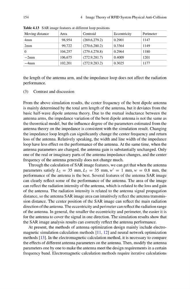
Table 4.13 SAR image features at different loop positions
Moving distance
Area
Centroid
Eccentricity
Perimeter
4mm
98,954
(269.6,279.2)
0.2901
1147
2mm
99,722
(270.6,280.2)
0.3364
1149
0
104,257
(279.4,278.8)
0.2964
1180
−2mm
106,675
(272.9,281.7)
0.4009
1201
−4mm
102,201
(272.9,283.2)
0.3025
1177
the length of the antenna arm, and the impedance loop does not affect the radiation
performance.
(3) Contrast and discussion
From the above simulation results, the center frequency of the bent dipole antenna
is mainly determined by the total arm length of the antenna, but it deviates from the
basic half-wave dipole antenna theory. Due to the mutual inductance between the
antenna arms, the impedance variation of the bent dipole antenna is not the same as
the theoretical model, but the influence degree of the parameters estimated from the
antenna theory on the impedance is consistent with the simulation result. Changing
the impedance loop length can significantly change the center frequency and return
loss of the antenna. Relatively speaking, the width and line width of the impedance
loop have less effect on the performance of the antenna. At the same time, when the
antenna parameters are changed, the antenna gain is substantially unchanged. Only
one of the real or imaginary parts of the antenna impedance changes, and the center
frequency of the antenna generally does not change much.
Through the calculation of SAR image features, we can get that when the antenna
parameters satisfy L 2 = 35 mm, L 3 = 35 mm, w
= 1 mm, w = 0.8 mm, the
performance of the antenna is the best. Several features of the antenna SAR image
can clearly reflect some of the performance of the antenna. The area of the image
can reflect the radiation intensity of the antenna, which is related to the loss and gain
of the antenna. The radiation intensity is related to the antenna signal propagation
distance, so the antenna SAR image area can intuitively reflect the antenna transmission distance. The center position of the SAR image can reflect the main radiation
direction of the antenna. The eccentricity and perimeter can reflect the radiation range
of the antenna. In general, the smaller the eccentricity and perimeter, the easier it is
for the antenna to cover the signal in one direction. The simulation results show that
the SAR image analysis results can correctly reflect the antenna performance.
At present, the methods of antenna optimization design mainly include electromagnetic simulation calculation methods [11, 12] and neural network optimization
methods [13]. In the electromagnetic calculation method, it is necessary to compare
the effects of different antenna parameters on the antenna. Then, modify the antenna
parameters one by one to make the antenna meet the design requirements in a certain
frequency band. Electromagnetic calculation methods require iterative calculations
4 Image Theory of RFID System Physical Anti-Collision
Table 4.13 SAR image features at different loop positions
Moving distance
Area
Centroid
Eccentricity
Perimeter
4mm
98,954
(269.6,279.2)
0.2901
1147
2mm
99,722
(270.6,280.2)
0.3364
1149
0
104,257
(279.4,278.8)
0.2964
1180
−2mm
106,675
(272.9,281.7)
0.4009
1201
−4mm
102,201
(272.9,283.2)
0.3025
1177
the length of the antenna arm, and the impedance loop does not affect the radiation
performance.
(3) Contrast and discussion
From the above simulation results, the center frequency of the bent dipole antenna
is mainly determined by the total arm length of the antenna, but it deviates from the
basic half-wave dipole antenna theory. Due to the mutual inductance between the
antenna arms, the impedance variation of the bent dipole antenna is not the same as
the theoretical model, but the influence degree of the parameters estimated from the
antenna theory on the impedance is consistent with the simulation result. Changing
the impedance loop length can significantly change the center frequency and return
loss of the antenna. Relatively speaking, the width and line width of the impedance
loop have less effect on the performance of the antenna. At the same time, when the
antenna parameters are changed, the antenna gain is substantially unchanged. Only
one of the real or imaginary parts of the antenna impedance changes, and the center
frequency of the antenna generally does not change much.
Through the calculation of SAR image features, we can get that when the antenna
parameters satisfy L 2 = 35 mm, L 3 = 35 mm, w
= 1 mm, w = 0.8 mm, the
performance of the antenna is the best. Several features of the antenna SAR image
can clearly reflect some of the performance of the antenna. The area of the image
can reflect the radiation intensity of the antenna, which is related to the loss and gain
of the antenna. The radiation intensity is related to the antenna signal propagation
distance, so the antenna SAR image area can intuitively reflect the antenna transmission distance. The center position of the SAR image can reflect the main radiation
direction of the antenna. The eccentricity and perimeter can reflect the radiation range
of the antenna. In general, the smaller the eccentricity and perimeter, the easier it is
for the antenna to cover the signal in one direction. The simulation results show that
the SAR image analysis results can correctly reflect the antenna performance.
At present, the methods of antenna optimization design mainly include electromagnetic simulation calculation methods [11, 12] and neural network optimization
methods [13]. In the electromagnetic calculation method, it is necessary to compare
the effects of different antenna parameters on the antenna. Then, modify the antenna
parameters one by one to make the antenna meet the design requirements in a certain
frequency band. Electromagnetic calculation methods require iterative calculations