

4.5 Novel Reverse Design Method of Tag Antenna Based on Image Analysis
147
adjust a certain parameter of the antenna model and use HFSS simulation to analyze
the change of antenna performance. We observe and analyze the specific effects of
each parameter on antenna performance.
(1) Antenna performance change analysis
(1) Analysis of the influence of antenna length on antenna performance
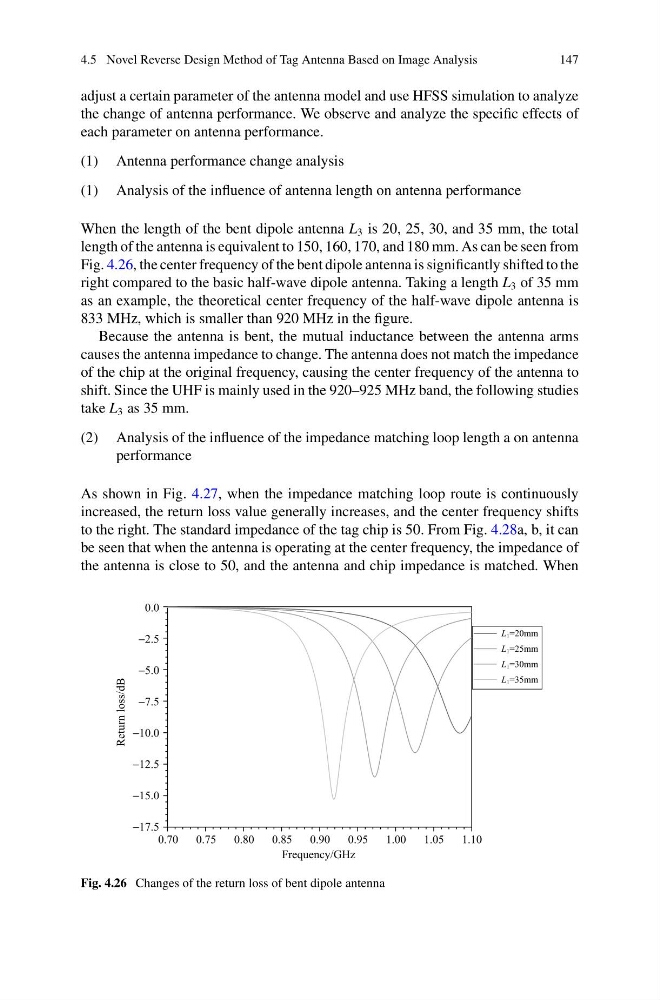
When the length of the bent dipole antenna L 3 is 20, 25, 30, and 35 mm, the total
length of the antenna is equivalent to 150, 160, 170, and 180 mm. As can be seen from
Fig. 4.26, the center frequency of the bent dipole antenna is significantly shifted to the
right compared to the basic half-wave dipole antenna. Taking a length L 3 of 35 mm
as an example, the theoretical center frequency of the half-wave dipole antenna is
833 MHz, which is smaller than 920 MHz in the figure.
Because the antenna is bent, the mutual inductance between the antenna arms
causes the antenna impedance to change. The antenna does not match the impedance
of the chip at the original frequency, causing the center frequency of the antenna to
shift. Since the UHF is mainly used in the 920–925 MHz band, the following studies
take L 3 as 35 mm.
(2) Analysis of the influence of the impedance matching loop length a on antenna
performance
As shown in Fig. 4.27, when the impedance matching loop route is continuously
increased, the return loss value generally increases, and the center frequency shifts
to the right. The standard impedance of the tag chip is 50. From Fig. 4.28a, b, it can
be seen that when the antenna is operating at the center frequency, the impedance of
the antenna is close to 50, and the antenna and chip impedance is matched. When
Fig. 4.26 Changes of the return loss of bent dipole antenna
147
adjust a certain parameter of the antenna model and use HFSS simulation to analyze
the change of antenna performance. We observe and analyze the specific effects of
each parameter on antenna performance.
(1) Antenna performance change analysis
(1) Analysis of the influence of antenna length on antenna performance
When the length of the bent dipole antenna L 3 is 20, 25, 30, and 35 mm, the total
length of the antenna is equivalent to 150, 160, 170, and 180 mm. As can be seen from
Fig. 4.26, the center frequency of the bent dipole antenna is significantly shifted to the
right compared to the basic half-wave dipole antenna. Taking a length L 3 of 35 mm
as an example, the theoretical center frequency of the half-wave dipole antenna is
833 MHz, which is smaller than 920 MHz in the figure.
Because the antenna is bent, the mutual inductance between the antenna arms
causes the antenna impedance to change. The antenna does not match the impedance
of the chip at the original frequency, causing the center frequency of the antenna to
shift. Since the UHF is mainly used in the 920–925 MHz band, the following studies
take L 3 as 35 mm.
(2) Analysis of the influence of the impedance matching loop length a on antenna
performance
As shown in Fig. 4.27, when the impedance matching loop route is continuously
increased, the return loss value generally increases, and the center frequency shifts
to the right. The standard impedance of the tag chip is 50. From Fig. 4.28a, b, it can
be seen that when the antenna is operating at the center frequency, the impedance of
the antenna is close to 50, and the antenna and chip impedance is matched. When
Fig. 4.26 Changes of the return loss of bent dipole antenna