

146
4 Image Theory of RFID System Physical Anti-Collision
in the target area,O(x, y) =
1νf (x, y) ∈ O
0, otherwise
, and the area of the image area is
calculated by Eq. (4.46):
A =
M −1
x=0
N −1
y=0
O(x, y)
(4.46)
The calculation formula for the position of the center of gravity of the image is
Eq. (4.47):
⎧
⎪ ⎪ ⎪ ⎪ ⎪ ⎨
⎪ ⎪ ⎪ ⎪ ⎪ ⎩
x =
1
A
M −1
x=0
N −1
y=0
xO(x, y)
y =
1
A
M −1
x=0
N −1
y=0
yO(x, y)
(4.47)
The perimeter is represented by an eight-way chain code, which is a method of
describing a curve or boundary using the coordinates of the starting point of the
curve and the direction code of the boundary point. The eccentricity is the ratio of
the distance between the focal points to the length of the long axis.
According to the requirements of the antenna performance in the experimental
application, the selection range of the eigenvalues of the antenna SAR image can be
determined, and the structural parameters of the antenna are reversely derived.
4.5.3 UHF RFID Tag Bend Dipole Antenna Analysis
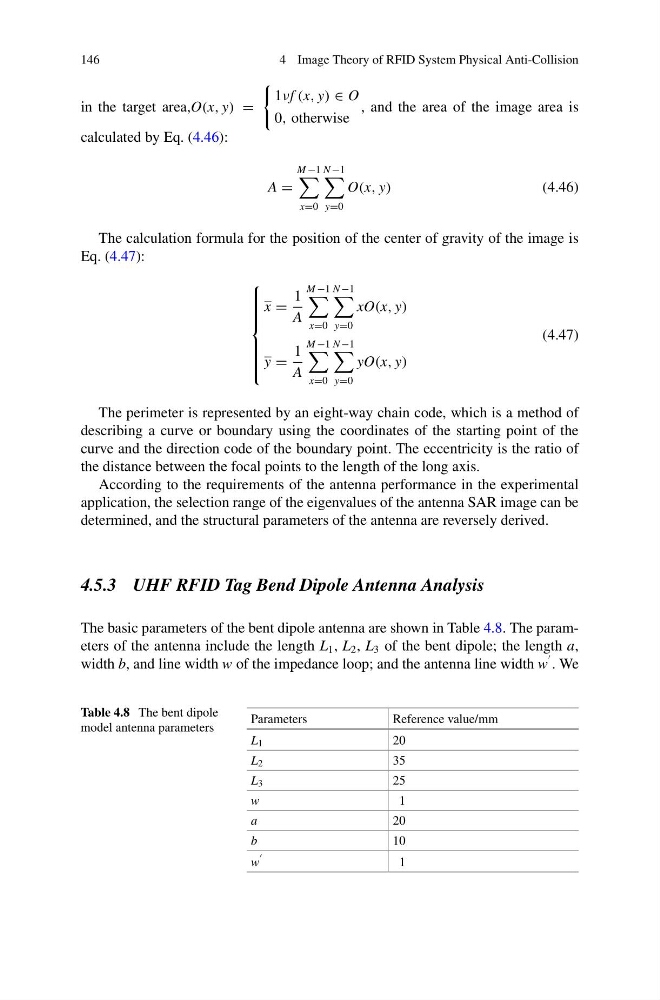
The basic parameters of the bent dipole antenna are shown in Table 4.8. The parameters of the antenna include the length L 1 , L 2 , L 3 of the bent dipole; the length a,
width b, and line width w of the impedance loop; and the antenna line width w
. We
Table 4.8 The bent dipole
model antenna parameters
Parameters
Reference value/mm
L 1
20
L 2
35
L 3
25
w
1
a
20
b
10
w
1
4 Image Theory of RFID System Physical Anti-Collision
in the target area,O(x, y) =
1νf (x, y) ∈ O
0, otherwise
, and the area of the image area is
calculated by Eq. (4.46):
A =
M −1
x=0
N −1
y=0
O(x, y)
(4.46)
The calculation formula for the position of the center of gravity of the image is
Eq. (4.47):
⎧
⎪ ⎪ ⎪ ⎪ ⎪ ⎨
⎪ ⎪ ⎪ ⎪ ⎪ ⎩
x =
1
A
M −1
x=0
N −1
y=0
xO(x, y)
y =
1
A
M −1
x=0
N −1
y=0
yO(x, y)
(4.47)
The perimeter is represented by an eight-way chain code, which is a method of
describing a curve or boundary using the coordinates of the starting point of the
curve and the direction code of the boundary point. The eccentricity is the ratio of
the distance between the focal points to the length of the long axis.
According to the requirements of the antenna performance in the experimental
application, the selection range of the eigenvalues of the antenna SAR image can be
determined, and the structural parameters of the antenna are reversely derived.
4.5.3 UHF RFID Tag Bend Dipole Antenna Analysis
The basic parameters of the bent dipole antenna are shown in Table 4.8. The parameters of the antenna include the length L 1 , L 2 , L 3 of the bent dipole; the length a,
width b, and line width w of the impedance loop; and the antenna line width w
. We
Table 4.8 The bent dipole
model antenna parameters
Parameters
Reference value/mm
L 1
20
L 2
35
L 3
25
w
1
a
20
b
10
w
1