

4.4 3D Space RFID Tag Location
139
as the origin, the distance r from the origin and the rotation angle θ n of any pattern
n have been obtained.
As shown in Fig. 4.21b, the polar coordinates that have been acquired can be
converted into two-dimensional horizontal coordinates. For the nth tag bracket
pattern, its two-dimensional coordinates (r n cos θ n , r n sin θ n ) can be obtained by its
r n and θ n .
After the horizontal position of all tags is measured, the turntable will rotate the
corresponding angle according to the horizontal position of each tag, so that the
tag can face the horizontal camera. The horizontal camera will automatically focus
according to the position of the tag to be measured to find the best collection point
to obtain the height information of the tag.
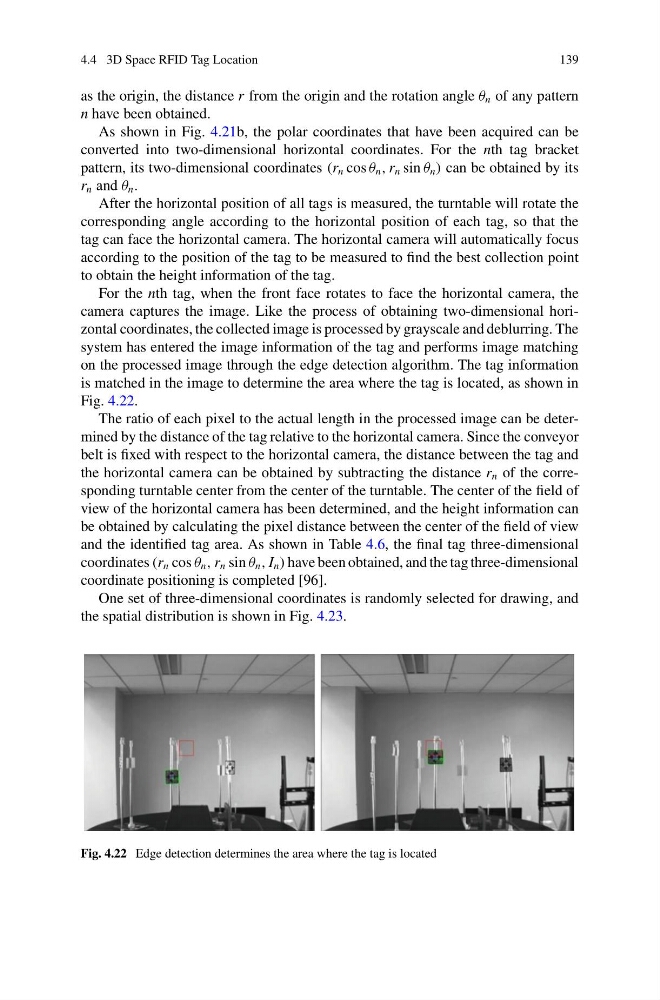
For the nth tag, when the front face rotates to face the horizontal camera, the
camera captures the image. Like the process of obtaining two-dimensional horizontal coordinates, the collected image is processed by grayscale and deblurring. The
system has entered the image information of the tag and performs image matching
on the processed image through the edge detection algorithm. The tag information
is matched in the image to determine the area where the tag is located, as shown in
Fig. 4.22.
The ratio of each pixel to the actual length in the processed image can be determined by the distance of the tag relative to the horizontal camera. Since the conveyor
belt is fixed with respect to the horizontal camera, the distance between the tag and
the horizontal camera can be obtained by subtracting the distance r n of the corresponding turntable center from the center of the turntable. The center of the field of
view of the horizontal camera has been determined, and the height information can
be obtained by calculating the pixel distance between the center of the field of view
and the identified tag area. As shown in Table 4.6, the final tag three-dimensional
coordinates (r n cos θ n , r n sin θ n , I n ) have been obtained, and the tag three-dimensional
coordinate positioning is completed [96].
One set of three-dimensional coordinates is randomly selected for drawing, and
the spatial distribution is shown in Fig. 4.23.
Fig. 4.22 Edge detection determines the area where the tag is located
139
as the origin, the distance r from the origin and the rotation angle θ n of any pattern
n have been obtained.
As shown in Fig. 4.21b, the polar coordinates that have been acquired can be
converted into two-dimensional horizontal coordinates. For the nth tag bracket
pattern, its two-dimensional coordinates (r n cos θ n , r n sin θ n ) can be obtained by its
r n and θ n .
After the horizontal position of all tags is measured, the turntable will rotate the
corresponding angle according to the horizontal position of each tag, so that the
tag can face the horizontal camera. The horizontal camera will automatically focus
according to the position of the tag to be measured to find the best collection point
to obtain the height information of the tag.
For the nth tag, when the front face rotates to face the horizontal camera, the
camera captures the image. Like the process of obtaining two-dimensional horizontal coordinates, the collected image is processed by grayscale and deblurring. The
system has entered the image information of the tag and performs image matching
on the processed image through the edge detection algorithm. The tag information
is matched in the image to determine the area where the tag is located, as shown in
Fig. 4.22.
The ratio of each pixel to the actual length in the processed image can be determined by the distance of the tag relative to the horizontal camera. Since the conveyor
belt is fixed with respect to the horizontal camera, the distance between the tag and
the horizontal camera can be obtained by subtracting the distance r n of the corresponding turntable center from the center of the turntable. The center of the field of
view of the horizontal camera has been determined, and the height information can
be obtained by calculating the pixel distance between the center of the field of view
and the identified tag area. As shown in Table 4.6, the final tag three-dimensional
coordinates (r n cos θ n , r n sin θ n , I n ) have been obtained, and the tag three-dimensional
coordinate positioning is completed [96].
One set of three-dimensional coordinates is randomly selected for drawing, and
the spatial distribution is shown in Fig. 4.23.
Fig. 4.22 Edge detection determines the area where the tag is located