

484
13 Preparation of Nanoporous Oxides from Metals by Electrochemical …
under the same conditions (solution composition, temperature and voltage) so that
the pore seeds do not need to rearrange and the regularity achieved during the first
anodization can be retained.
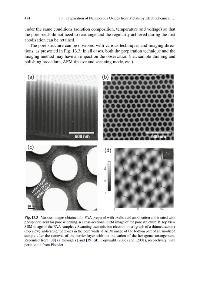
The pore structure can be observed with various techniques and imaging directions, as presented in Fig. 13.3. In all cases, both the preparation technique and the
imaging method may have an impact on the observation (i.e., sample thinning and
polishing procedure, AFM tip size and scanning mode, etc.).
Fig. 13.3 Various images obtained for PAA prepared with oxalic acid anodization and treated with
phosphoric acid for pore widening. a Cross-sectional SEM image of the pore structure; b Top view
SEM image of the PAA sample; c Scanning transmission electron micrograph of a thinned sample
(top view), indicating the zones in the pore walls; d AFM image of the bottom part of an anodized
sample after the removal of the barrier layer with the indication of the hexagonal arrangement.
Reprinted from [38] (a through c) and [39] (d). Copyright (2006) and (2001), respectively, with
permission from Elsevier
13 Preparation of Nanoporous Oxides from Metals by Electrochemical …
under the same conditions (solution composition, temperature and voltage) so that
the pore seeds do not need to rearrange and the regularity achieved during the first
anodization can be retained.
The pore structure can be observed with various techniques and imaging directions, as presented in Fig. 13.3. In all cases, both the preparation technique and the
imaging method may have an impact on the observation (i.e., sample thinning and
polishing procedure, AFM tip size and scanning mode, etc.).
Fig. 13.3 Various images obtained for PAA prepared with oxalic acid anodization and treated with
phosphoric acid for pore widening. a Cross-sectional SEM image of the pore structure; b Top view
SEM image of the PAA sample; c Scanning transmission electron micrograph of a thinned sample
(top view), indicating the zones in the pore walls; d AFM image of the bottom part of an anodized
sample after the removal of the barrier layer with the indication of the hexagonal arrangement.
Reprinted from [38] (a through c) and [39] (d). Copyright (2006) and (2001), respectively, with
permission from Elsevier