

530
I. Cr⸠stiu et al.
4 Experimental Results
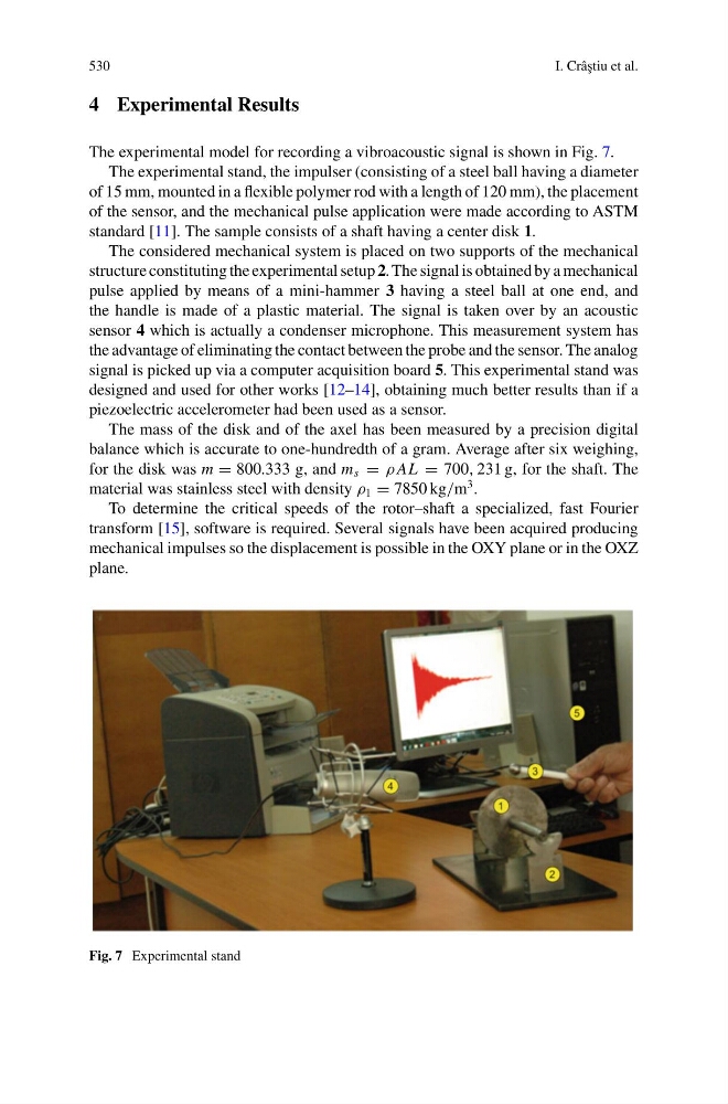
The experimental model for recording a vibroacoustic signal is shown in Fig. 7.
The experimental stand, the impulser (consisting of a steel ball having a diameter
of 15 mm, mounted in a flexible polymer rod with a length of 120 mm), the placement
of the sensor, and the mechanical pulse application were made according to ASTM
standard [11]. The sample consists of a shaft having a center disk 1.
The considered mechanical system is placed on two supports of the mechanical
structure constituting the experimental setup 2. The signal is obtained by a mechanical
pulse applied by means of a mini-hammer 3 having a steel ball at one end, and
the handle is made of a plastic material. The signal is taken over by an acoustic
sensor 4 which is actually a condenser microphone. This measurement system has
the advantage of eliminating the contact between the probe and the sensor. The analog
signal is picked up via a computer acquisition board 5. This experimental stand was
designed and used for other works [12–14], obtaining much better results than if a
piezoelectric accelerometer had been used as a sensor.
The mass of the disk and of the axel has been measured by a precision digital
balance which is accurate to one-hundredth of a gram. Average after six weighing,
for the disk was m = 800.333 g, and m s = ρ AL = 700, 231 g, for the shaft. The
material was stainless steel with density ρ 1 = 7850 kg/m
3 .
To determine the critical speeds of the rotor–shaft a specialized, fast Fourier
transform [15], software is required. Several signals have been acquired producing
mechanical impulses so the displacement is possible in the OXY plane or in the OXZ
plane.
Fig. 7 Experimental stand
I. Cr⸠stiu et al.
4 Experimental Results
The experimental model for recording a vibroacoustic signal is shown in Fig. 7.
The experimental stand, the impulser (consisting of a steel ball having a diameter
of 15 mm, mounted in a flexible polymer rod with a length of 120 mm), the placement
of the sensor, and the mechanical pulse application were made according to ASTM
standard [11]. The sample consists of a shaft having a center disk 1.
The considered mechanical system is placed on two supports of the mechanical
structure constituting the experimental setup 2. The signal is obtained by a mechanical
pulse applied by means of a mini-hammer 3 having a steel ball at one end, and
the handle is made of a plastic material. The signal is taken over by an acoustic
sensor 4 which is actually a condenser microphone. This measurement system has
the advantage of eliminating the contact between the probe and the sensor. The analog
signal is picked up via a computer acquisition board 5. This experimental stand was
designed and used for other works [12–14], obtaining much better results than if a
piezoelectric accelerometer had been used as a sensor.
The mass of the disk and of the axel has been measured by a precision digital
balance which is accurate to one-hundredth of a gram. Average after six weighing,
for the disk was m = 800.333 g, and m s = ρ AL = 700, 231 g, for the shaft. The
material was stainless steel with density ρ 1 = 7850 kg/m
3 .
To determine the critical speeds of the rotor–shaft a specialized, fast Fourier
transform [15], software is required. Several signals have been acquired producing
mechanical impulses so the displacement is possible in the OXY plane or in the OXZ
plane.
Fig. 7 Experimental stand